Configuring the TPI
37
TPI-PRO-DVI - Instruction Manual
Conf iguring the TPI
Overview
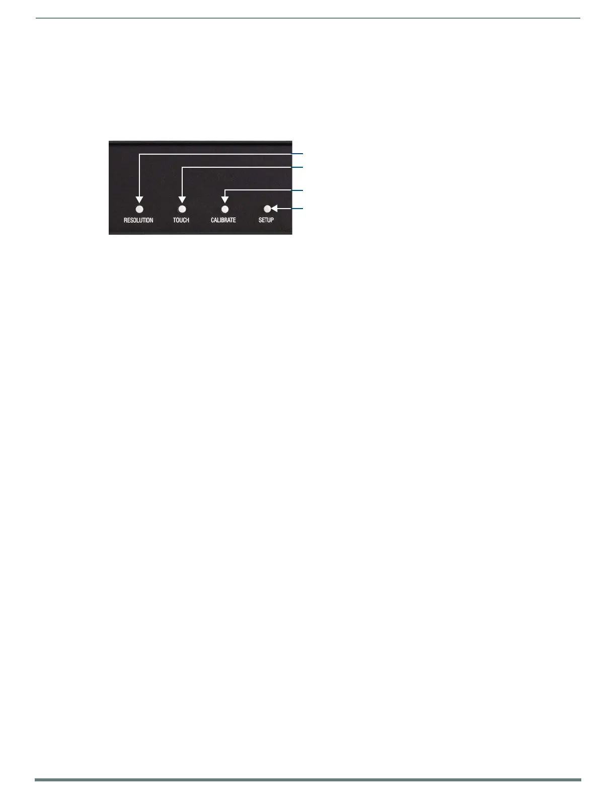
The TPI features four configuration pushbuttons (RESOLUTION, TOUCH, CALIBRATE and SETUP) on the front panel (FIG. 30). These
pushbuttons provide quick access to the main configuration pages for the TPI, as described in the following sections:
The information contained within this section refers to the procedures necessary to set up the TPI resolution, assign a touch driver,
and calibrate the driver for use with a connected touch monitor.
NOTE: In order to configure the TPI, you’ll need to have a touch device as well as an output display device connected, so that you can
view and navigate the pages and make selections and text entries. See the Wiring and Device Connections section on page 24 for
details.
The configuration options described in this section are limited to the functions and settings that are typically necessary for the
initial setup of the TPI.
There are many more configuration options available:
Refer to the TPI Configuration Pages section on page 52 for full descriptions of every Configuration page and the options
contained in each.
Refer to the Protected Setup Page section on page 64 for descriptions of the options available via the Protected Setup
Pages.
Before You Start
The TPI has been factory setup with specific touch panel pages. The first splash screen that appears indicates the TPI is receiving
power, loading firmware, and preparing to display the default touch panel page. When the panel is ready, the AMX Splash Screen is
replaced by the Initial Panel Setup page.
Verify you are using the latest NetLinx Master firmware.
Verify you are using the latest TPI firmware.
Verify the NetLinx Studio program you are using is version 2.8 or higher.
Verify the TPDesign4 program you are using is version 2.11 or higher.
Startup Routine and Initial Panel Response
Discharge any acquired static electricity by touching a grounded metal object.
Verify the rear connections are secure and active. Refer to the Rear Panel Connectors section on page 26 for detailed cable
connector information.
1. Connect the 12VDC Power Supply to the PWR connector on the rear panel. The TPI will power ON and initialize the startup
routine when the power supply is connected.
NOTE: Once power is applied, use the Power button to toggle the unit off and on.
2. After the startup routine, the connected touch monitor displays one of two possible screens:
If the TPI’s output resolution matches that of the touch monitor, continue by setting the touch drivers associated with the
touch monitor.
Refer to the Setting the Touch Drivers (Serial Touch Monitors Only) section on page 38.
If the TPI’s output resolution does not match the resolution of the connected touch monitor, you must set the output
resolution of the TPI to match the touch monitor.
Refer to the following section - Setting the Output Resolution.
NOTE: An "OUT OF RANGE" message is often generated by the touch monitor. Some monitors will not display a message, but will
appear blank instead.
FIG. 30
Configuration Pushbuttons (front panel)
Press to open the Resolution Setup page
Press to open the Panel Information page
Press to open the Calibration page
Press to open the Setup page
(including Touch Input Driver setting / information)
 Loading...