System Installation
32
TPI-PRO-DVI - Instruction Manual
System Installation
Overview
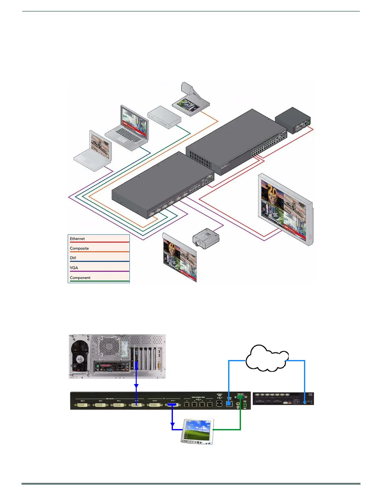
FIG. 24 illustrates a typical TPI-PRO-DVI installation:
The following System Diagrams illustrate common applications for the TPI-PRO-DVI. For detailed pinout descriptions for each
connector on the TPI, refer to the Rear Panel Connectors section on page 26.
Touch Input via Touch Monitor
FIG. 25 illustrates a typical installation using a Serial touch monitor to display output from a video source (in this case, a PC).
FIG. 26 illustrates a typical installation using a USB touch monitor to display output from a video source.
FIG. 24
System Diagram
FIG. 25 Example 1: TOUCH INPUT (Serial Touch Monitor)
document camera
DVD player
Apple notebook
Laptop PC
NXA-ENET24
NI-700
TPI-PRO-DVI
display screen
projector
projection screen
TPI OUTPUT 1 connects to VGA touch monitor
(via DVI-to-VGA adapter cable)
Touch input Serial connector on touch monito
connects to TOUCH INPUT on TPI (via Serial c
PC
DVI output from PC
LAN
NetLinx Master
connects to TPI INPUT 1
Touch Monitor
 Loading...