Section 7 Communication (Modbus)
7-4
Communication
(Modbus)
7.2 Frames
Based on the Modbus (RTU) communication protocol, commands from the host computer and responses
from the E5AR/ER take the form of frames.
The data comprising command frames and response frames are explained below.
In the following explanation, an "H'" at the beginning of a numeric value (for example H'02) indicates that
the value is a hexadecimal number. A number or letters enclosed in quotation marks (for example "00") is
an ASCII character.
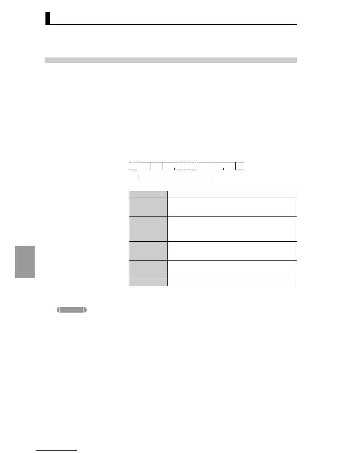
■ Command frame In RTU mode each frame begins and ends with a silent time interval
that is at least 3.5 characters long.
● Example of CRC-16
calculation
CRC-16 calculation method:
As indicated at right, the value
from the client address to the
end of the data is calculated
and the result set in CRC-16.
The following explains how a message is processed 1 byte at a time in
the processing register (this is a 16-bit register called the "CRC
register").
(1) Set an initial value of H'FFFF in the CRC register.
(2) Perform XOR on the CRC register and the 1st byte of the message, and
return the result to the CRC register.
(3) Shift the contents of the CRC register 1 bit to the right, filling the MSB with
"0".
(4) If the bit shifted from the LSB is "0", repeat step (3).
If the bit shifted from the LSB is "1", perform XOR on the CRC register and
H'A001, and return the result to the CRC register.
(5) Repeat steps (3) and (4) until the contents of the register have been
shifted 8 bits to the right.
Silent interval at least 3.5 characters long.
Client address
Specify the "Unit No." of the E5AR/ER. Set in hexadecimal
from H'00 to H'63 (0 to 99). When broadcasting to all units,
specify H'00. Responses are not returned to a broadcast.
Function code
The function code indicates the type of command from the
host computer. The code is set in hexadecimal and is 1
byte long. For more information, see "7.3 List of functions"
(P.7-7).
Data
Text of command based on the function code. Specifies
variable addresses and the values of setting data (specify
in hexadecimal).
CRC-16
Cyclical Redundancy Check. This is a check code calcu-
lated from the client address to the end of the data. Two
bytes in hexadecimal.
Silent interval at least 3.5 characters long.
Slave
address
Function
mode
CRC-16 calculation range
11
CRC-16
Data
2 bytes
Supplement