3.4 Cascade control of reflow ovens
3-15
Typical Control
Examples
3. Press the M key repeatedly to select "mode: Control mode". Press the U
to select "5: Cascade standard control".
4. Hold down the L at least 1 second to return to "RUN level". "PV/SP/MV"
will appear. Press the U key to set the SP to "180.0".
■ Adjustment
(1) Run AT in the secondary loop to obtain suitable PID values.
When the primary loop achieves stable control close to the SP, set the
secondary local SP to the secondary PV.
Set the SP mode of channel 2 to local SP mode (cascade open), and with
the secondary loop in the independent control state, run AT.
When AT finishes, obtain the secondary PID values.
(2) Set the control mode to cascade control, and run AT on the primary loop
to obtain the primary PID values.
Set the primary SP to local SP.
Set the SP mode of channel 2 to remote SP mode (cascade control),
switch to cascade control, and run AT.
When finished, check the primary and secondary control states (PVs)
and manually adjust the PID values. Use the same adjustment method
as regular PID control.
1. After the power is turned on, "PV/SP/MV" of the primary loop appears (ch 1).
(Here we assume that cascade control is in progress using near SP of
180.0
°C)
2. Press the key to select the secondary (ch 2) "PV/SP/MV". The RSP
operation indicator lights on to indicate that the system is in the cascade
control (cascade closed) state.
(Here we assume that the secondary PV is 230.0
°C. The secondary local
SP will be set to 230.0°C in step 5.)
mode
1
0
l.1
Control mode
5
U
23.0
1
0.0
0.0
RUN level
Present value
(
PV
)
/ SP /
MV
180.0
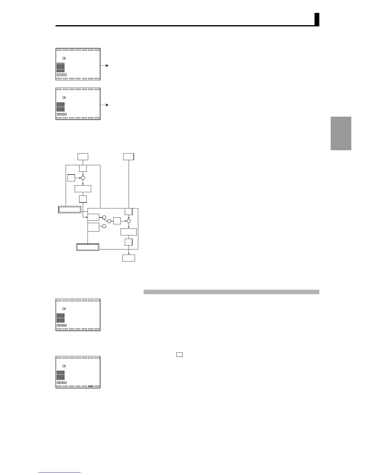
U
IN1
PV
+
-
SP
Channel 1
PID*
MV
IN2
RSP
Local SP
(
LSP
)
PV
+
-
SP
Channel 2
PID*
Remote SP
Local SP
MV
OUT1
182.0
1
180.0
30.0
RUN level
Present value
(
PV
)
/ SP /
MV
CH
230.0
2
250.0
50.0
Ch 2
RSP
Present value
(
PV
)
/ SP /
MV
 Loading...


