Section 7 Communication (Modbus)
7-8
Communication
(Modbus)
7.4 Variable area
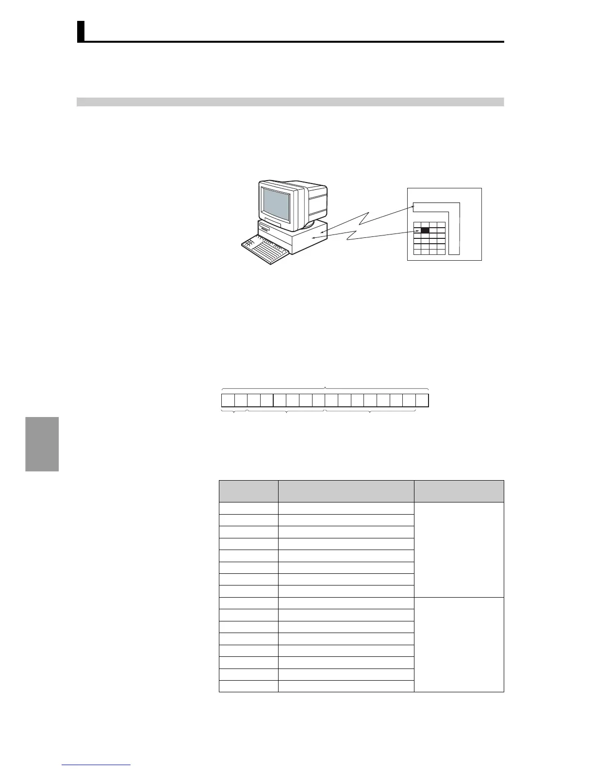
The area used for data exchange when communicating with the E5AR/ER is called the "variable area".
The PV is read and various setting data are read and written using the variable area of the E5AR/ER.
Operation commands do not use the variable area.
The variable area is accessed by specifying the position of a variable
within the variable area using a channel identifier, area number, and
in-area address.
● Address
(Communication/
Modbus)
Each variable type has an address. Each address is two bytes long
and expressed in hexadecimal. Assign addresses according to units of
access size. An address consists of a channel identifier, area number,
and in-area address.
Area numbers
Area numbers in the variable area are as follows:
Microprocessor
E5AR/ER
Variable area
Operation
instruction, etc.
Read/write
Variable
type
Description Area
04 Communication monitor
Setting area 0
(Operation in
progress)
05 Protect level
06 RUN level
07 Adjustment level
08 Adjustment level 2
09 Bank setting level
0A PID setting level
0B Approximation setting level
0C Input initial setting level
Setting area 1
(Operation stopped)
0D Control initial setting level
0E Control initial setting 2 level
0F Alarm setting level
10 Display adjustment level
11 Communications setting level
12 Special function setting level
13 Expansion control setting level
##∗∗∗∗∗∗
0
A6 A5 A4 A3 A2 A1 A0
Address (2 bytes)
Channel
indentifiers
(0 to 3)
Address in area (00 to FE)
Area number (00 to 3F)
 Loading...


