4.11 Using auxiliary output
4-25
Settings Required
for Basic Control
* When using SP ramp, an alarm will activate during RUN with
respect to the SP after ramping, and during STOP an alarm will
activate with respect to the SP.
■ Alarm values
Alarm values are indicated by "X" in the alarm type table. When
separate upper and lower limit alarm values are set, the upper limit
value is indicated by "H" and the lower limit is indicated by "L".
When upper- and lower-limit, upper- and lower-limit range, or lower
limit alarm with standby sequence is selected, the "Alarm upper limit"
and "Alarm lower limit" settings must be configured.
"Alarm value" must be configured when any other alarm type is
selected.
■ Settings
To output an alarm to the auxiliary output, the "Auxiliary output
assignment", "Alarm type" and "Alarm value" settings must be
configured.
Outputting a lower limit alarm to auxiliary output 2 using CH 1 alarm 1
and an alarm value of 10.0°C
Auxiliary output 2
assignment
The following explains how to set "Auxiliary output 2 assignment" to
"CH 1 alarm 1" in "Control initial setting level 2"
1. Hold down the L key at least 3 seconds to move from "RUN level" to
"Input initial setting level".
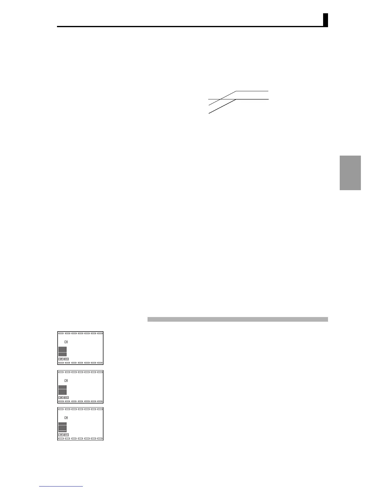
2. In "Input initial setting level", Display 3 shows "l.0".
Press the L key twice (less than 1 second each time) to move to "Control
initial setting 2 level".
3. In "Control initial setting 2 level", Display 3 shows "l.2".
Press the M key repeatedly (less than 1 second each time) to select
"Auxiliary output 2 assignment".
SP
SP after ramp
Operating point of alarm
(upper-limit alarm)
25.0
1
150.0
0.0
i1-t
1
2
l.0
out.1
1
1
l.2
 Loading...


