7.2 Frames
7-5
Communication
(Modbus)
(6) If the end of the message has not been reached, perform XOR on the next
byte of the CRC register and the message, return the result to the CRC
register, and repeat the procedure from step (3).
(7) Append the result (the value in the CRC register) to the lower byte of the
message.
Example of appending the result
If the calculated CRC value is H'1234, this is appended as follows to the
command frame.
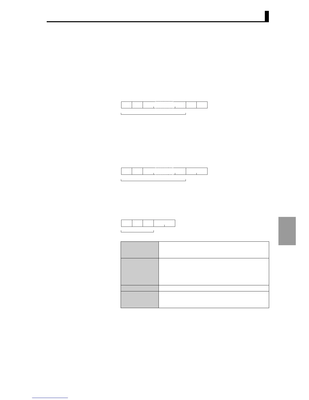
■ Response frame
● Normal response frame
● Error response frame
Slave
address
Function
mode
CRC-16 calculation range
11
CRC-16
Low
H’34
High
H’12
Data
2 bytes
Slave
address
Function
mode
CRC-16 calculation range
11
CRC-16
Data
2 bytes
Client address
The number that was specified in the command frame
appears here. This is the unit number of the responding
E5AR/ER.
Function code
The function code that was received.
In an error response frame, "H'80" is added to the value
to indicate that this is an error response.
Example: Received function code = H'03
Function code in error response frame = H'83
Error code End code that indicates the error.
CRC-16
Cyclical Redundancy Check. This is a check code calcu-
lated from the client address to the end of the data. Two
bytes in hexadecimal.
CRC-16 calculation range
Slave
address
Function
mode
Error
code
CRC-16
2 bytes111