10.2 Error messages
10-3
Troubleshooting
10.2 Error messages
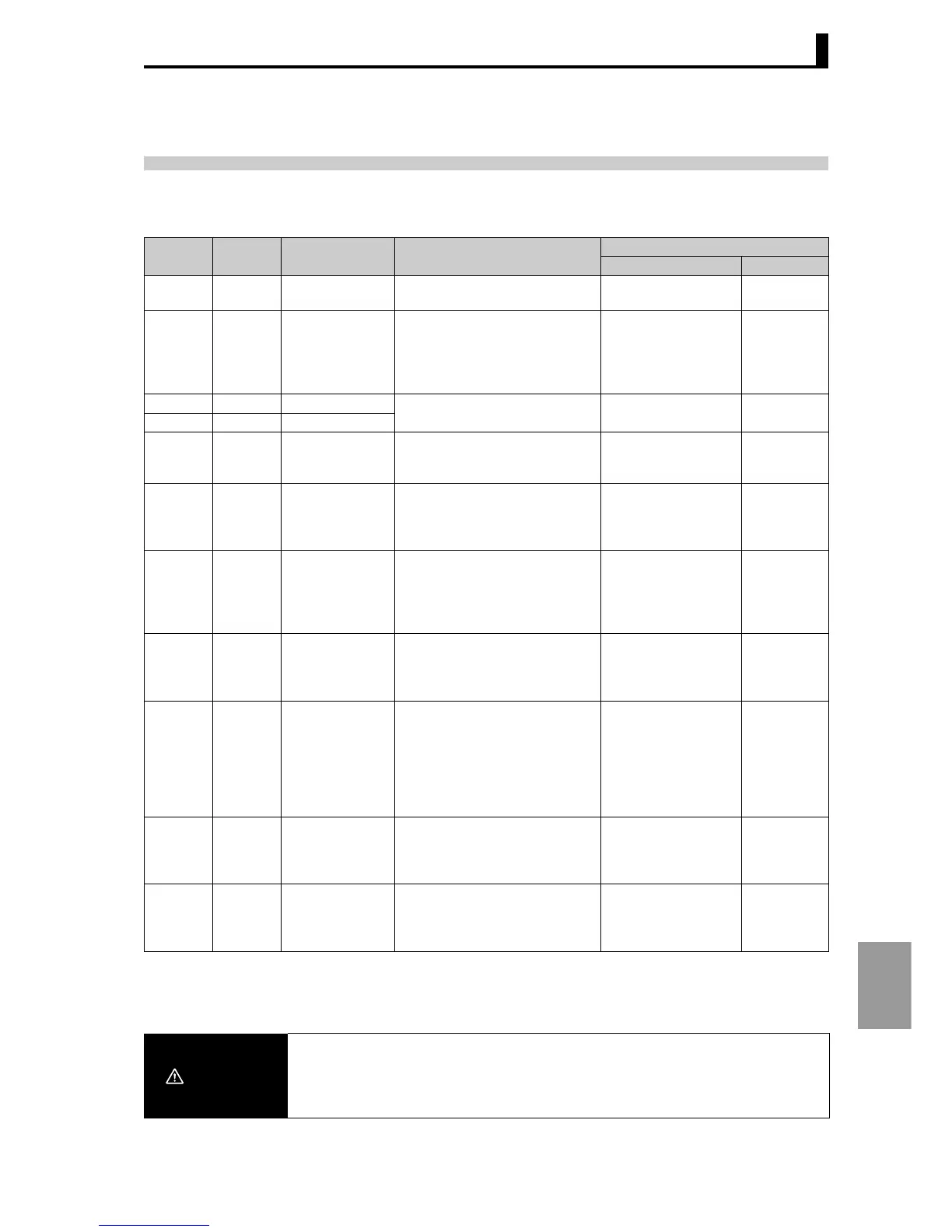
When an error occurs, Displays 1 and 2 show error messages.
Refer to the following table to check the meaning of the message and how to solve the problem.
If the system does not operate as expected after configuring settings, check the wiring and set values
once again. If there is still a problem, unintended set values may have been accidentally configured in the
setting data. In this case, you can initialize the unit and then re-configure your settings.
∗
Display 1 Display 2 Error Solution
Output state at error
Control output Alarm output
unit err Unit error The unit requires service. Please
contact your dealer.
OFF OFF
unit chg Unit change
Hold down the
L
key for at least 5
seconds to store the current unit
configuration.
If this does not clear the error
display, please contact your dealer.
OFF OFF
disp err Display unit error
Service is required. Please
consult your dealer.
OFF OFF
sys err Unit error
eep err Non-volatile
memory error
Hold down the L key for at least
5 seconds in the error display to
initialize. *
OFF OFF
s.err Normal
display
Input error
Check for an incorrect input
connection, broken wire, or short-
circuit. Check the input type and
input type switch settings.
MV output according
to "MV at PV error"
setting.
"Upper limit
exceeded"
operation.
[[[[[
]]]]]
Normal
display
Exceeds display
range (lower line)
Exceeds display
range (upper
line)
Not an error; however, appears
when PV exceeds the display
range (-19999 to 99999). Normal operation
Normal
operation
Normal
display
RSP
operation
indicator
blinks
RSP input error Is the wire connected to the RSP
input broken or short-circuited?
MV at PV error OFF
Normal
display
----- Potentiometer
input error
Check the potentiometer wiring.
When "Closed/Floating"
is closed and "operation
at potentiometer input
error" is OFF, an error
MV is output; at all
other times, normal
operation takes place.
Normal
operation
calb err Motor calibration
error
Check the wiring to the
potentiometer and valve drive
motor, and then try motor
calibration again.
OFF OFF
i1-t
i2-t
i3-t
i4-t
Set value
blinks
Input type switch
error
Set the input type switch for the
input you are using so that it
accords with the displayed "Input
type" setting.
OFF OFF
Caution
Initializing the unit will return all settings to the factory default settings. The fac-
tory default settings may cause unexpected output, so disconnect all output
wires and eliminate effects to the system before initializing the unit. In addition,
write down your settings prior to initialization.
 Loading...


