Section 7 Communication (Modbus)
7-12
Communication
(Modbus)
7.6 Writing to the variable area
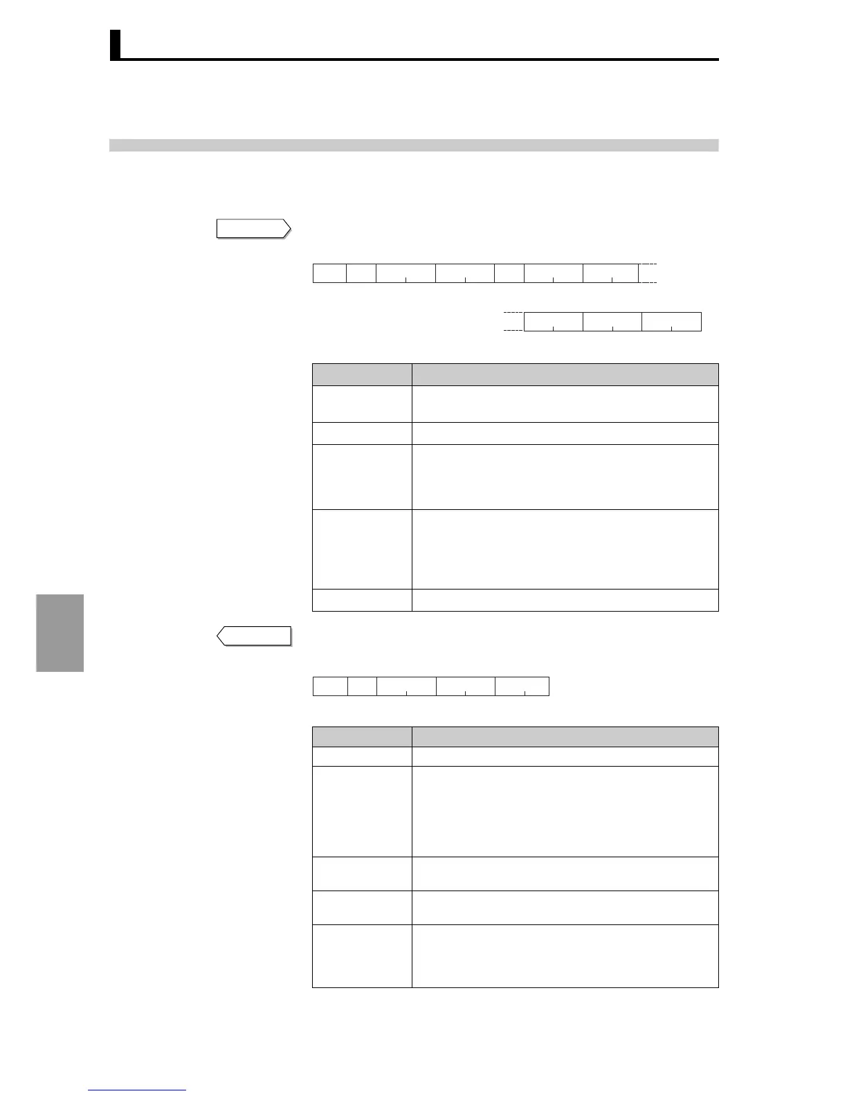
Write to the variable area by setting the required data in the following command frame.
Command frame
FINS-mini response text
Data name Explanation
Client address
Specify the "Unit No." of the E5AR/ER. Set in hexadeci-
mal from H'01 to H'63 (1 to 99).
Function mode The function code for variable area write is H' 10.
First address of
write
Specify the address of the setting data to which you wish
to write.
For more information on addresses, see "Appendix Set-
ting list" (P.A-6).
Number of
elements
Specify the number of setting data items that you wish to
write × 2 for the number of elements. The setting range
is H'0002 to H'0068 (2 to 104).
Example: When the number of setting data items is 2,
specify H' 0004.
Byte count Specify the number of bytes of data to be written.
Data name Explanation
Client address The value from the command frame appears here.
Function mode
This is the received function code.
In an error response frame, "H'80" is added to the
received function code to indicate that it is an error
response.
Example: Received function code = H'10
Function code in error response frame = H'90
Beginning
address of write
Beginning address of write that was received.
Number of
elements
Received number of elements.
CRC-16
This is a check code calculated from the client address
to the data end. For the calculation method, see "7.2
Frames ■ Command frame ● Example of CRC-16 cal-
culation" (P.7-4).
Command
H’10
Slave
address
Function
mode
Byte
count
Write start
address
Write dataNumber of
elements Data 1 Data 1
Data n Data n CRC-16
2
Most significant Least significant
Most significant Least significant
Number of elements × 2 bytes12 211
Response
H’10
Slave
address
Function
mode
Write start
address
Number of
elements
CRC-16
22211
 Loading...


