9.3 Thermocouple input calibration
9-5
User calibration
9.3 Thermocouple input calibration
• Thermocouples are calibrated in two groups according to thermocouple type: Group 1 (input types 2, 4,
7, 8, 10, 14) and Group 2 (input types 3, 5, 6, 9, 11, 12, 13).
• Do not cover the bottom of the thermocouple during calibration. Also, do not touch the input terminal or
compensation wire.
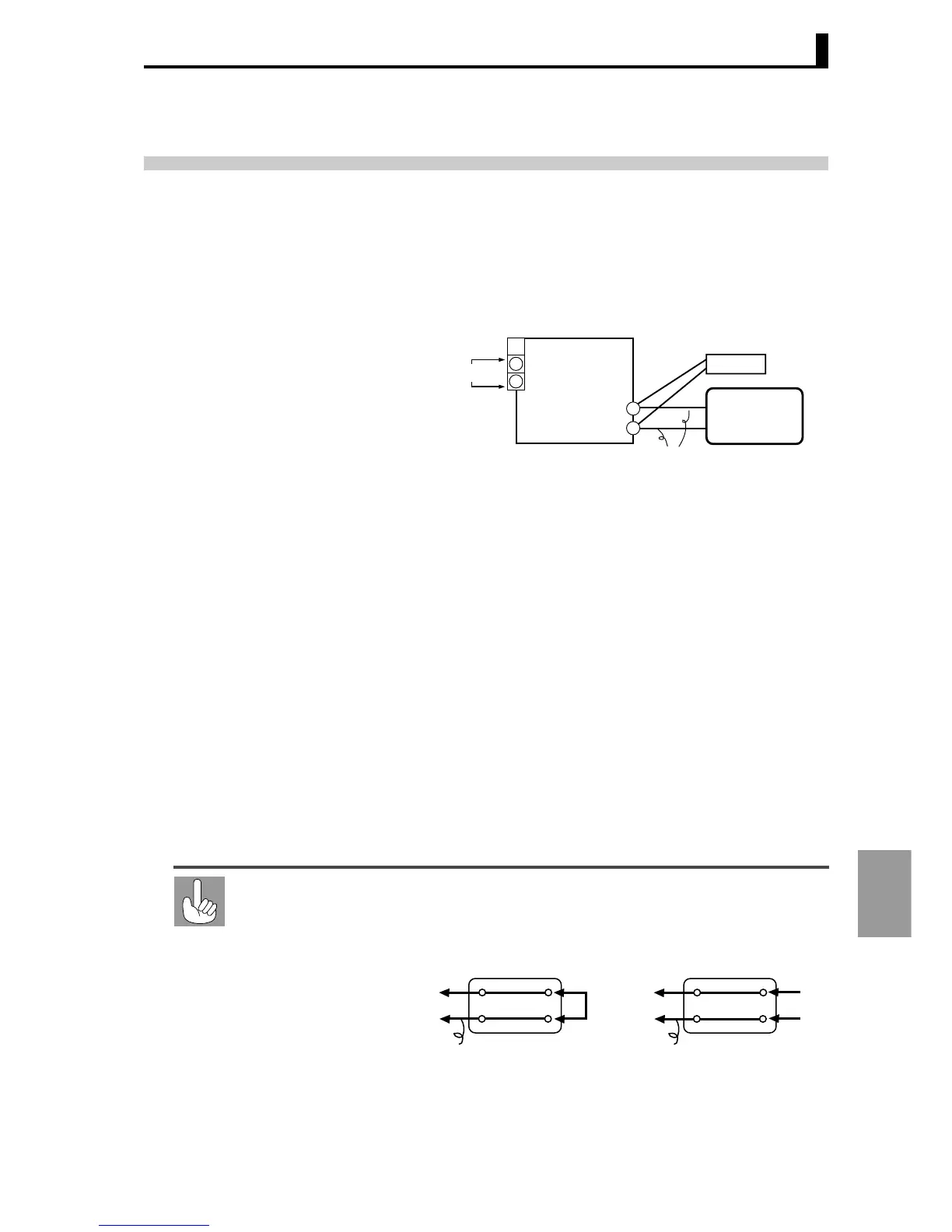
● Preparations
• For the cold junction compensator, use a compensator for calibration
of internal thermocouples and set to 0°C. The internal thermocouple
should be disabled (tip open).
• STV in the diagram indicates a DC reference current/voltage
generator.
• Prepare a compensation wire appropriate for the selected thermo-
couple. For thermocouples R, S, E, B and W, a cold junction
compensator and compensation wire for thermocouple K can be
used.
Connecting the cold
junction compensator
A correct input value cannot be obtained if the compensation wire connector is
touched during thermocouple calibration. Therefore, to connect or disconnect
the cold junction compensator, short-circuit (enable) or open-circuit (disable)
the tip of the thermocouple inside the cold junction compensator, while keeping
the compensation wire connected as shown in the diagram.
Cold junction
compensator
E5AR/E5ER
Compensating wire
STV
0°C/32°F
5
6
Input power supply
_
+
1
A
2
Cold junction compensator
Short circuit
Open
Compensating wire
E5AR/ER
E5AR/ER
0°C/32°F
Cold junction compensator
Compensating wire
0°C/32°F
 Loading...


