Section 9 User calibration
9-10
User calibration
9.5 Resistance temperature input sensor calibration
The procedure for calibrating a resistance temperature input sensor is
explained in the following.
For the connection wiring, use wiring of the same thickness.
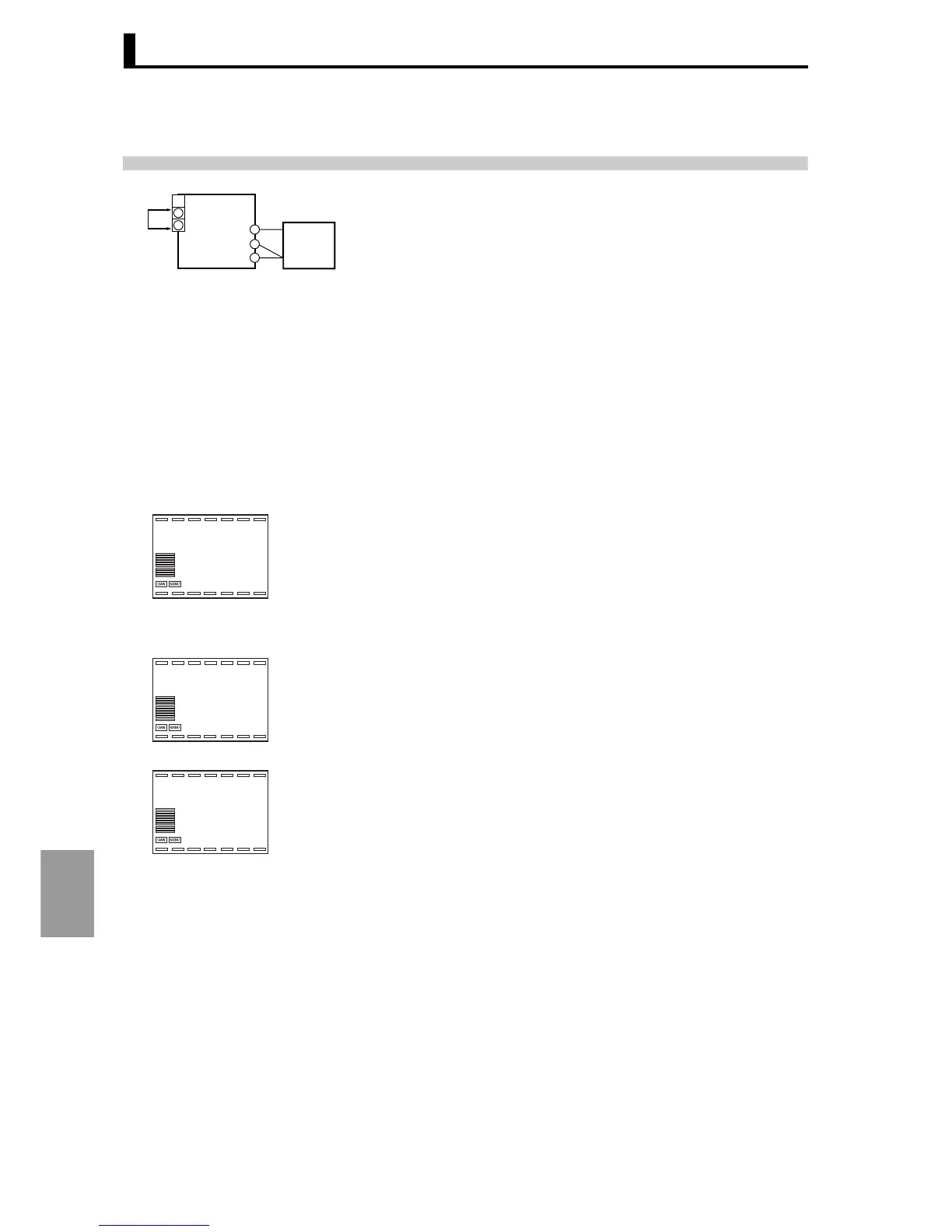
1. Connect the power supply.
2. Connect a precision resistance box (6-dial in the following) to the input
terminal of the resistance temperature input sensor as shown at left.
3. Turn on the power.
4. Move to calibration level.
A 30-minute aging time begins. Perform aging using this time as a
guideline. When 30 minutes elapses, Display 2 will show "0".
Note that you can proceed to the next stop before the display shows "0".
5. Press the key M to display the count value for each input type.
At this time the count value that was input will appear in Display 2 in
hexadecimal. Set the 6-dial as follows:
• Input type 0: 390 Ω
• Input type 1: 160 Ω
6. Wait until the count in Display 2 is sufficiently stable and then press the D
key. This tentatively saves the calibration data at this point.
E5AR/E5ER
A
B
B
6 dial
Input
power
supply
1
A
2
5
4
6
adj
30
l.cal
p390.1
86228
l.cal
Input type 0
p160.1
76288
l.cal
Input type 1
 Loading...


