EasyManua.ls Logo

Omron E5AR - MANUAL 2 User Manual

Omron E5AR - MANUAL 2
343 pages
To Next Page IconTo Next Page
To Previous Page IconTo Previous Page
Page #187 background imageLoading...
Page #187 background image
Section 7 Communication (Modbus)
7-14
Communication
(Modbus)
7.7 Operation commands (Communication/Modbus)
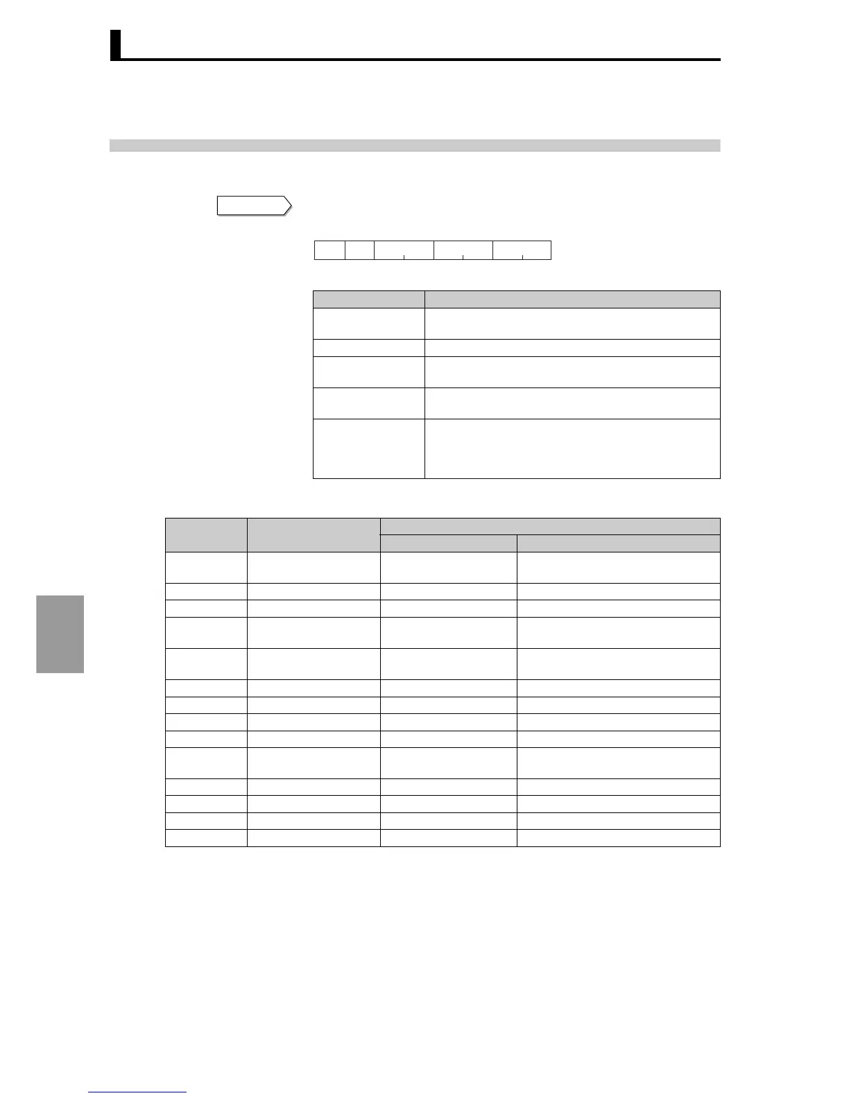
Operation commands are sent using the following command frame.
Command frame
Operation commands for the E5AR/ER are shown in the following.
*1: Operates for all channels.
*2: Specify for each channel
0: CH1, 1: CH2, 2: CH3, 3: CH4, F: All channels
*: There is no response to a software reset.
*: When all channels are specified, only enabled channels will respond and processing will begin from
Channel 1. If an error is detected on any one channel, an "Operation error" will result. If all channels
end normally, "Normal end" results.
Data name Explanation
Client address
Specify the "Unit No." of the E5AR/ER. Set in hexa-
decimal from H'01 to H'63 (1 to 99).
Function mode The function code for an operation command is H' 06.
Beginning
address of write
Specify H' 0000 for the operation command address.
Data written
Enter the command code of the operation command
and related information (see table below).
CRC-16
This is a check code calculated from the client
address to the data end. For the calculation method,
see "7.2 Frames Command frame Example of
CRC-16 calculation" (P.7-4).
Command
H’06 H’00 H’00
Slave
address
Function
mode
Write start
address Write data
CRC-16
2 bytes2211
Operation
code
Description
Related information
Upper Byte Lower Byte
H'00
Write via communication
H'0 *1
H'0: OFF (Disabled)
H'1: ON (Enabled)
H'01 Run/Stop H'0 to 3, F *2 H'0: Run H'1: Stop
H'02 Bank change H'0 to 3, F *2 H'0 to 7: Bank 0 to 7
H'03 AT run H'0 to 3, F *2
H'0: Currently selected PID Set No.
H'1 to 8: PID Set No.
H'04 Write mode H'0 *1
H'0: Backup mode
H'1: RAM write mode
H'05 RAM data save H'0 *1 H'0
H'06 Software reset H'0 *1 H'0
H'07 Move to setting area 1 H'0 *1 H'0
H'08 Move to protect level H'0 *1 H'0
H'09 Auto/Manual H'0 to 3, F *2
H'0: Auto mode
H'1: Manual mode
H'0A AT stop H'0 to 3, F *2 H'0: Stop
H'0B Initialize settings H'0 *1 H'0
H'0C Cancel latch H'0 to 3, F *2 H'0
H'0D SP mode H'0 to 3, F *2 H'0: LSP H'1: RSP

Table of Contents

Question and Answer IconNeed help?

Do you have a question about the Omron E5AR - MANUAL 2 and is the answer not in the manual?

Omron E5AR - MANUAL 2 Specifications

General IconGeneral
BrandOmron
ModelE5AR - MANUAL 2
CategoryController
LanguageEnglish

Summary

Introduction

Precaution in using the product

Important safety precautions and guidelines for using the controller under specific conditions.

Warranty and Limitations of Liability

Application Considerations

Precautions

Precautions for Safe Use

Precautions for Correct Use

Section 1 Overview

1.3 Input/output Configuration and Main Functions

Diagrams and explanations of input/output configurations and the controller's main functions.

Section 4 Settings Required for Basic Control

4.1 Setting levels and key operation

Explanation of the controller's setting levels and the keys used for navigation and operation.

4.3 Initial setting examples

Step-by-step examples for configuring initial settings like sensor input type and control mode.

Section 5 Functions and Operations

5.1 Input adjustment functions

Functions for adjusting input signals, including input shift, first order lag, and move average.

5.2 Control functions

Explanation of advanced control functions like SP ramp, banks, and PID sets.

Section 6 Communication (CompoWay/F)

Section 7 Communication (Modbus)

Section 8 Setting data

Section 9 User calibration

9.3 Thermocouple input calibration

Step-by-step guide for calibrating thermocouple inputs, including preparations and procedures.

Section 10 Troubleshooting

10.1 Troubleshooting checklist

A systematic checklist to help identify the cause of controller malfunctions.

10.2 Error messages

Explanation of error messages displayed by the controller and their solutions.

Related product manuals