1.3 Input/output Configuration and Main Functions
1-7
Overview
1.3 Input/output Configuration and Main Functions
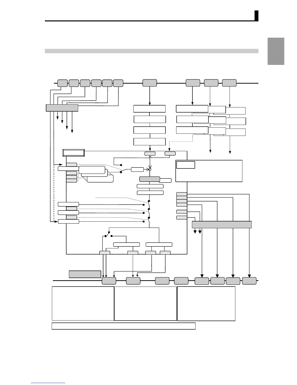
■ Input/output configuration
The input/output configuration of the E5AR/ER and internal setting item are shown in the following diagram
.
* Cascade standard control, Cascade heating/cooling control, position proportional control and ratio
control are also available. See "Section 3, Typical Control Examples" (page 3-1).
Extraction of
square root 4
First order
lag operation 4
Move average 4
Extraction of
square root 3
First order
lag operation 3
Move average 3
Bank No. 7
Local SP, Alarm value, PID set
Bank No. 1
Local SP, Alarm value, PID set
Bank No. 0
Local SP, Alarm value, PID set
Remote SP
Local SP
−
+
PV.1
RSP.1
RNRS.1
LRSP.1
MNAT.1
BNK0.1
BNK1.1
BNK2.1
MV at stop
Manual MV
Local SP
MV at PV error
SP ramp
Manual
Auto
Stop
Run
Error
MV change rate limiter
MV limiter
Input error
Remote SP input error
Potentiometer input error
ALM4.1
ALM3.1
ALM2.1
ALM1.1
SERR.1
RSER.1
Extraction of
square root 1
First order
lag operation 1
PV.1
RSP.1
MVH.1
MVL.1
VLVO.1
VLVC.1
EV1
IN1
OUT1 OUT2
SUB1
SUB2
SUB3
SUB4
Move average 1
IN2
OUT3 OUT4
EV2 EV3 EV4 EV5 EV6
IN3 IN4
MVC.1
VLVO.1 VLVC.1
Standard type Position proportional type
Position proportional dead band
Dead band
Standard control
Heating/cooling control
[SP mode]
"Control mode"
Input type switch
"Input type"
"Temperature units"
"Scaling"
Control / Transfer
output assignments
Extraction of
square root
2
First order
lag operation 2
Move average 2
Direct/reverse action
PID
"Control mode" is control with remote SP
Event input assignment
Control mode
Channel 1
Local/Remote SP mode
Channel 1 bank (bit 0)
Channel 1 bank (bit 1)
Channel 1 bank (bit 2)
Channel 1 RUN/STOP
Channel 1 manual/auto
ALM1.1
ALM2.1
ALM3.1
ALM4.1
SERR.1
RSER.1
Channel 1 Alarm 1
Channel 1 Alarm 2
Channel 1 Alarm 3
Channel 1 Alarm 4
Channel 1 Input error
Channel 1 Remote SP input error
MVH.1
Channel 1
Auxiliary output assignments
Multi-point input types have the same setting data for channels 2 to 4 depending on the number of input points.
Broken-line
approximation 1
∗
Standard control
Heating/cooling control
Standard control with remote SP
Heating/cooling control with remote SP
Channel 1 PV
Channel 1 Remote SP
Channel 1 MV (heating side)
Channel 1 MV (cooling side)
Channel 1 MV (open side)
Channel 1 MV (closed side)
LRSP.1
BNK0.1
BNK1.1
BNK2.1
RNRS.1
MNAT.1
=
 Loading...


