3.5 Ratio control of dyeing machines
3-19
Typical Control
Examples
■ Wiring
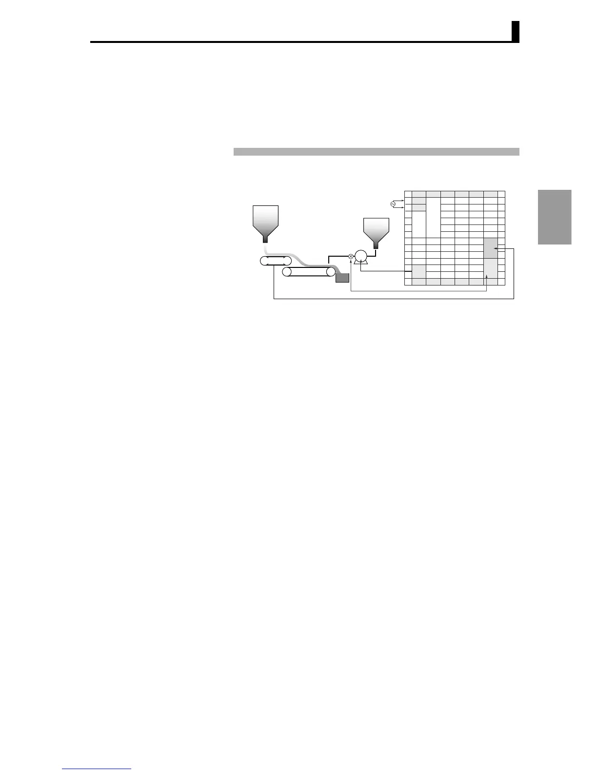
IN1 is connected to the adjustment system and IN2 is connected to the
sensor in the reference system. (A flow meter is connected to IN1, a
sand weight scale is connected to IN2, and a pump (drive inverter) is
connected to OUT1.)
When using the E5AR-QQ43W-FLK, wire as shown below.
■ Settings
The scale of sensor 1, which measures the flow of dye, is 0.0 to 25.0
kg/s, and the scale of sensor 2, which measures the weight of sand, is
0.0 to 500.0 kg/s. The ratio value is set to 0.05 so that the proportion of
sand to dye will be 110 : 5.
Related setting data and settings are as follows:
Input 1 type switch = ANALOG
Input 2 type switch = ANALOG
Input 1 type = 15: 4 to 20 mA
Ch 1 scaling input value 1 = 4
Ch 1 scaling display value 1 = 0
Ch 1 scaling input value 2 = 20
Ch 1 scaling display value 2 = 250
Ch 1 decimal point position = 1
Input 2 input type = 15: 4 to 20 mA
Output type of output 1 = 1: Current output (initial setting)
Output type of linear current output 1
= 1: 4 to 20 mA (initial setting)
Control mode = 4: Ratio control
Straight-line approximation 1 = on: Enable
Straight-line approximation 2 = on: Enable
Straight-line approximation 1, Straight-line approximation 2
→ See the setting examples on the next page
Analog parameter 1 = 0.05
SP mode = rsp: Remote SP
ABCDE
1
2
3
4
5
6
1
2
3
4
5
6
1
2
3
4
5
6
1
2
3
4
5
6
FGHI JK
IN2
IN1
OUT1
Sensor 2
100 - 240 V AC
Sensor 2 flow meter
Color liquid
Sand
P
4 - 20 mA
Sand weight meter
 Loading...


