2.2 How to Use the Terminals
2-11
Preparations
■ Precautions when wiring
• To avoid the effects of noise, wire the signal wires and the power line
separately.
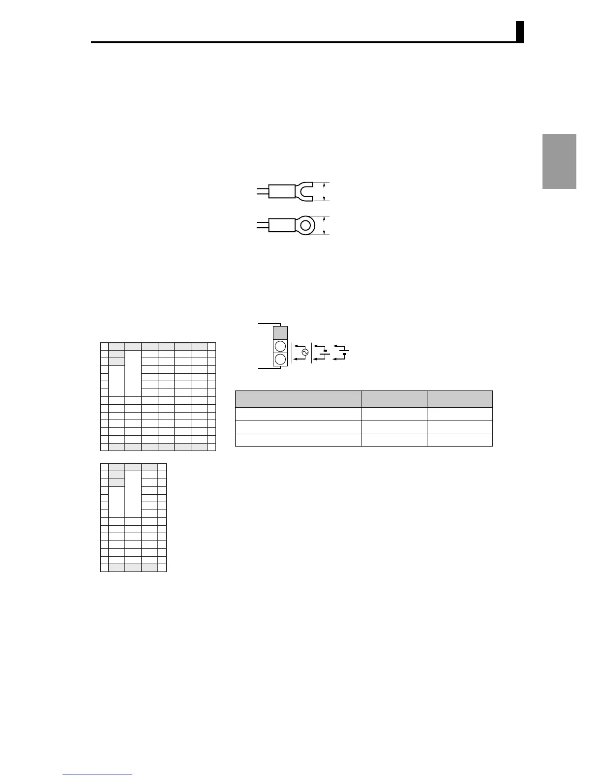
• Use crimp terminals to connect to the terminals.
• Tighten screws to a torque of 0.40 to 0.56 N
•m.
• The crimp terminals should be type M3 and either of the following
shapes:
■ Wiring
The inside of the frame around terminal numbers in the schematics
indicates the interior of the unit, and the outside of the frame indicates
the exterior.
● Power supply
(terminals)
• Connect terminals A1 to A2 as follows:
The input power supply varies
depending on the model.
100-240 V AC or 24 V AC/DC (no
polarity)
5.8 mm or less
5.8 mm or less
1
2
3
4
5
6
1
2
3
4
5
6
1
2
3
4
5
6
1
2
3
4
5
6
A B C D E
FGHI J K
1
2
3
4
5
6
1
2
3
4
5
6
1
2
3
4
5
6
1
2
3
4
5
6
AB
CDE
E5AR
E5ER
+
+
-
-
1
2
A
Input voltage E5AR E5ER
100-240 V AC 50/60Hz 22 VA 17 VA
24 V AC 50/60Hz 15 VA 11 VA
24 V DC (no polarity) 10 W 7 W
 Loading...


