3 System Setup
3 - 22 Instructions for Use
Input/Output Panel Connections
Audio and video connections are located on the Input/Output (I/O) panel. An Ethernet (network)
port is located on the inside of the input/output panel door. Two additional USB ports are
located on the back of the control panel.
WARNING: Accessory equipment connected to the analog and digital interfaces must be
certified according to the respective EN and IEC standards (for example, EN 60950 and
IEC 60950 for data processing equipment and IEC 60601-1 for medical equipment). Anyone
who connects additional equipment to any of the signal input or signal output ports configures a
medical system and is therefore responsible that the system complies with the requirements of
the system standards IEC 60601-1. Siemens can only guarantee the performance and safety of
the devices listed in the Instructions for Use. If in doubt, consult the Siemens service department
or your local Siemens representative.
Caution: To ensure proper grounding and leakage current levels, it is the policy of Siemens to
have an authorized Siemens representative or approved third party perform all on-board
connections of documentation and storage devices to the ultrasound system.
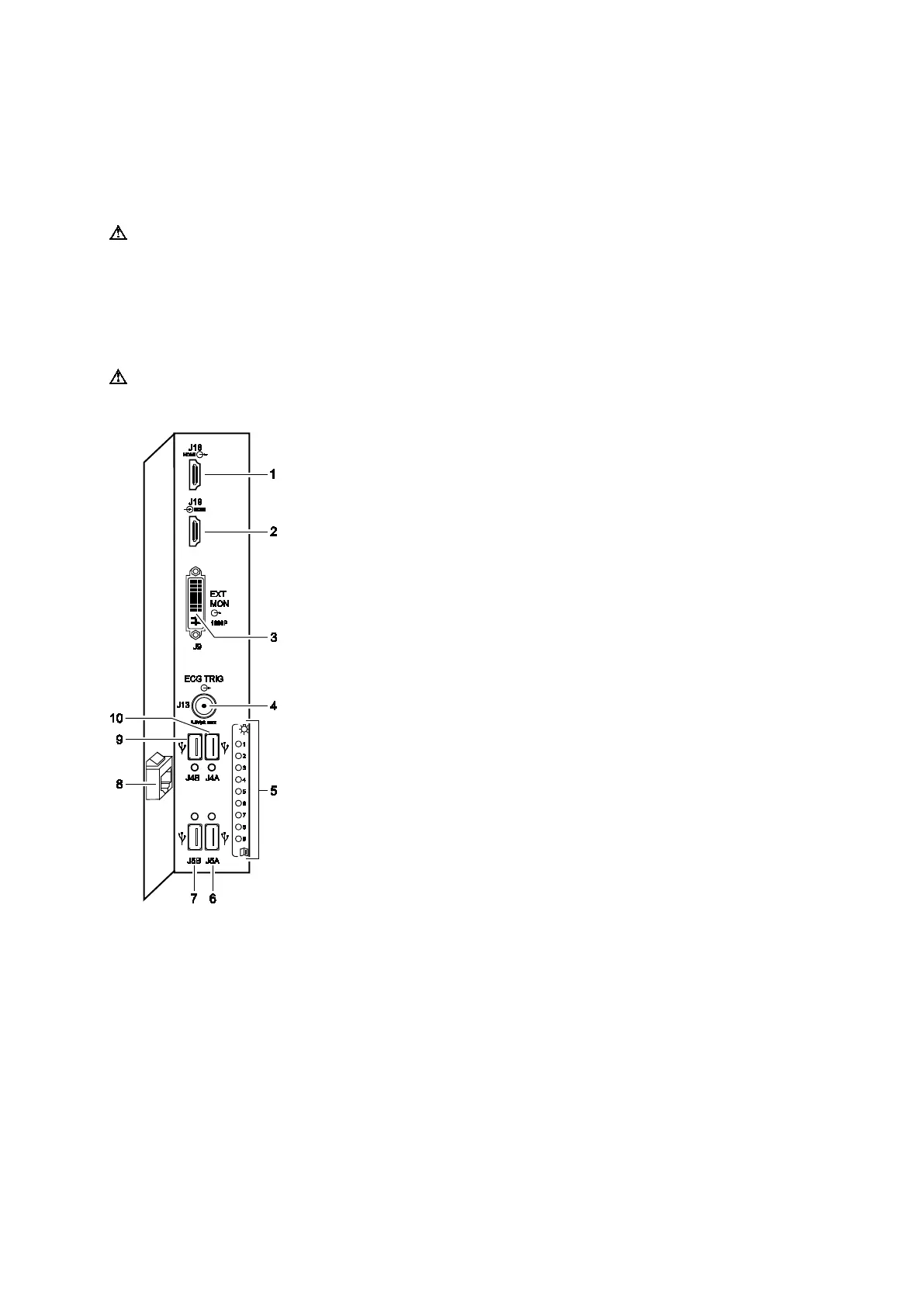
1 HDMI port, J18: video recorder (video and audio output)
2 HDMI port, J19: video recorder (video and audio input)
3 DVI port, J9: external monitor (digital or analog output)
4 BNC-type port, J13: ECG trigger (output)
5 System status LEDs
6 USB-A port, J5A: printer or USB storage device
7 USB-A port, J5B: printer, SIE1 data transmission, or USB
storage device
8 RJ-45 port: Ethernet (10BaseT/100BaseT/1000BaseT)
9 USB-A port, J4B: video recorder (remote control) or USB
storage device
10 USB-A port, J4A: USB storage device
Example of input/output panel ports and connections.
 Loading...


