Wiring Diagrams 10-25
Paper Exit
Signal line name Description
/SOS Synchronization signal generated by SOS Sensor. This signal
commands start of each scan.
/PCONT Sample / Hold circuit
Low: Sampled (LD is forcibly lit up); High: Held
Vref Laser output control signal for determining or adjusting the current
flowing through Laser Diode.
MO/DET-OUT Laser output monitor signal for providing feedback of laser output beam
from Laser Diode (analog signal).
/LDENB Control signal permitting emission of Laser Diode.
High: Laser Diode OFF.
XP DATA+ Print image data. DATA+ > DATA-: lit up
DATA+ < DATA-: put out
XP DATA-
/ROSMOT ON Sensor Motor Control signal for turning Scanner Motor ON/OFF.
Low: ON / High: OFF
/ROSMOT CLK Clock signal to Laser Unit Motor.
Signal line name Description
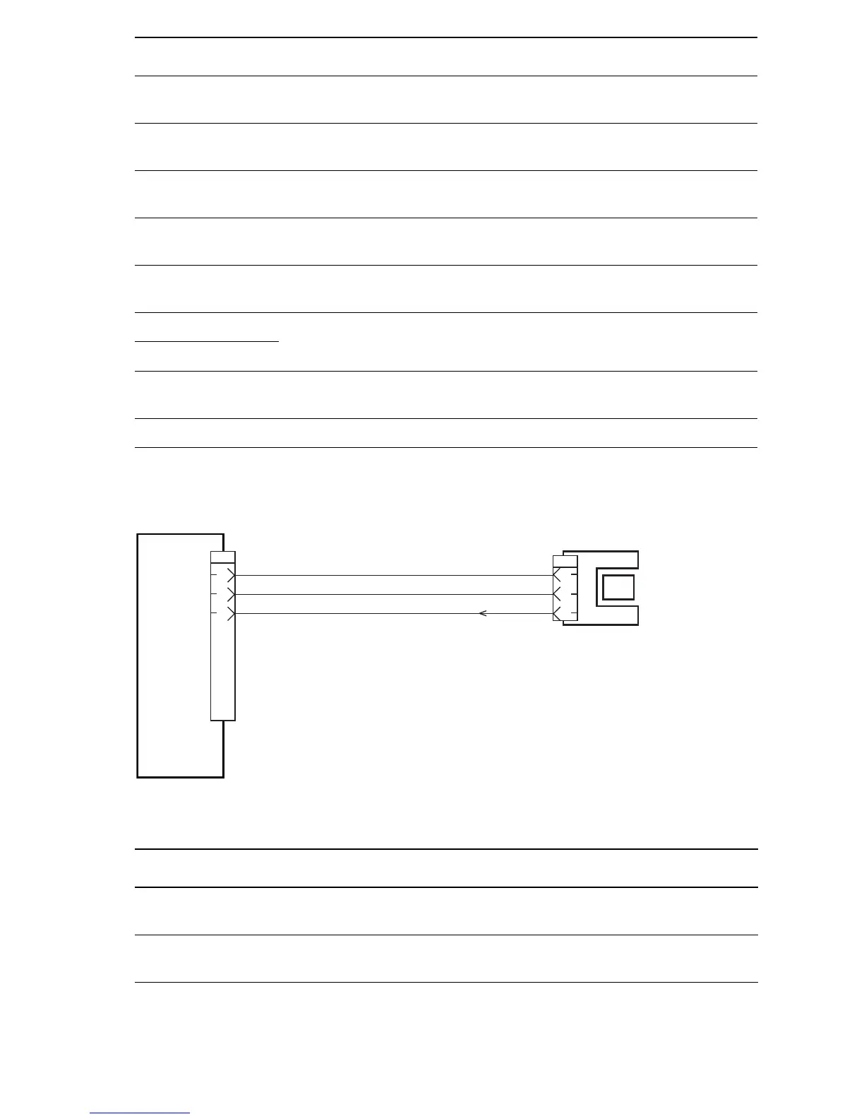
/FULLSTACK SNR ON Signal from Stack Full Sensor. This signal goes Low when the flag
moves out of the sensor.
/FACE UP OPEN SNR ON Signal from Face-Up Open Sensor. This signal goes Low when
the flag moves out of the sensor.
P/J29
2
3
1
HVPS/
ENGINE
LOGIC
PWBA
EXIT SENSOR
HARNESS
STACK FULL
SENSOR
2
1
3
P/J290
Pull Up 3.3V
LG
/ FULLSTACK SNR ON
s4500-240
 Loading...


