10-32 Phaser 4500 Service Manual
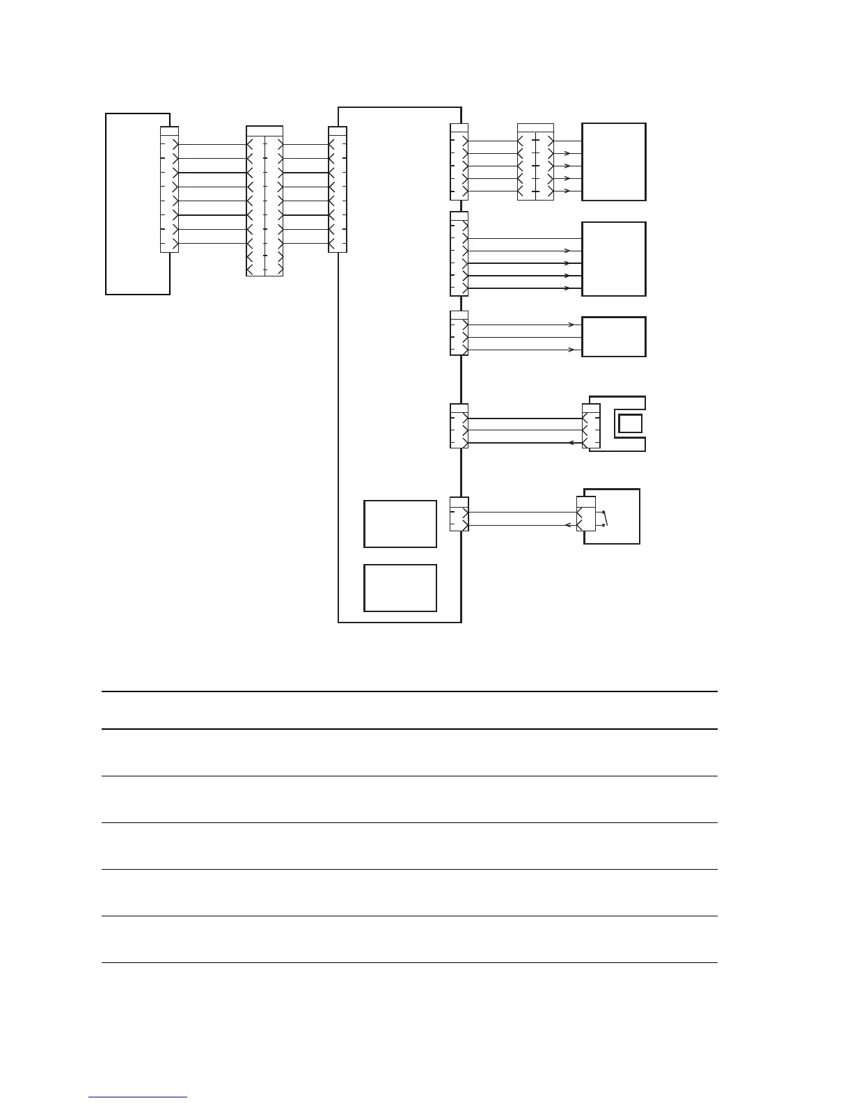
Stacker Signal Diagram
Signal line name Description
A and B Excitation signal for Stacker Motor Assembly and MOTOR Assembly.
Phases A and B.
/A and /B Excitation signal for MOTOR Assembly Stacker and Offset Motor
Assembly. Phases /A and /B.
DIR SOL FUKKI
DIR SOL KYUIN
Control signal for Gate Solenoid Assembly.
/OCT SNR ON Signal from Duplex Unit Sensor. This signal goes Low when the flag
moves out of the sensor.
/REAR Top Cover Signal from Rear Cover Switch. This signal goes Low when the rear
cover of Stacker (Rear Cover) is closed.
7
6
5
4
3
2
1
8
2
3
4
5
6
7
8
9
10
1
2
3
4
5
6
7
8
9
10
1
P/J30
2
3
4
5
6
7
8
1
P/J70
2
3
4
5
1
P/J71
24V DC
A
B
/A
/B
P/J3070
24V DC
RTN
RTN
LG
TXD
RXD
N.C.
N.C.
N.C.
N.C.
N.C.
24V DC
3.3V DC
Stacker
PWBA
Stacker
Harness 2
Stacker
Harness 1
Stacker
Motor
Offset
Motor
Gate
Solenoid
Stacker Sensor
Harness
Stacker Motor
Harness
Rear Cover
Harness
Stacker
Sensor
Stacker Rear
Cover Switch
Full Stack
Sensor
Offset
Sensor
2
3
4
5
6
1
P/J72
24V DC
A
B
/A
/B
2
1
3
P/J75
2
3
1
P/J73
1
2
P/J74
2
1
3
P/J730
DIR SOL FUKKI
DIR SOL KYUIN
24V DC
Pull Up 3.3V
LG
LG
/ REAR COVER OPEN
/ OCT SNR ON
1
2
P/J740
4
3
2
1
5
s4500-246
2
3
4
5
1
P/J710
HVPS/
Engine
Logic
PWBA
 Loading...


