January 2016
3-8
WorkCentre WorkCentre 4150/4250/4260WorkCentre 4150/4250/42604150/
IQ1, IQ2
Image Quality
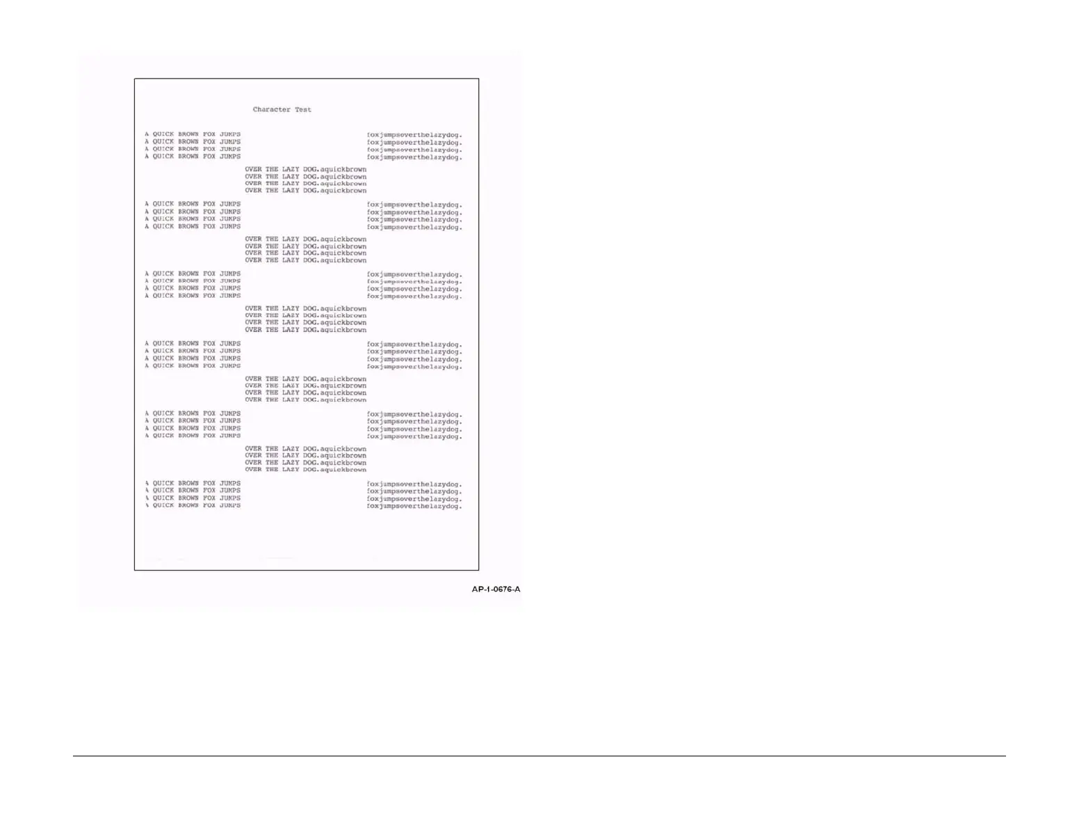
Figure 7 Test pattern 8 and 16
IQ2 Blank Copies RAP
Use this RAP when the machine produces blank copies.
Procedure
WARNING
Switch off the electricity to the machine. Disconnect the power cord from the customer
supply while performing tasks that do not need electricity. Electricity can cause death or
injury. Moving parts can cause injury.
1. Determine the source of the problem. Make a print. Make a copy.
2. If the defect appears only in copy mode, perform the following:
a. Ensure the DADF is closed. Room illumination can be transmitted through thin origi-
nals.
b. If the defect appears only when using the DADF, check that the scanner lock is com-
pletely unlocked.
c. Perform ADJ 14.1 Shading Adjustment.
3. If the defect appears in all modes, perform the following:
a. Examine the toner cartridge, PL 9.10 Item 2 and xerographic module, PL 9.10 Item
1. Ensure they are free from all packing or sealing material.
b. Check the LSU. Go to the 06-100, 200 LSU Error RAP.
c. (4150) Refer to Wiring Diagram 3. Perform the following:
• Check the wiring between the LSU and CN5 on the Main PWB.
• Install a new LSU, PL 6.10 Item 1.
d. (4250) Refer to Wiring Diagram 32. Perform the following:
• Check the wiring between the LSU and CN39 on the Main PWB.
• Install a new LSU, PL 6.10 Item 1.
e. (4260) Refer to Wiring Diagram 21. Perform the following:
• Check the wiring between the LSU and CN4 on the Main PWB.
• Install a new LSU, PL 6.10 Item 1.
f. (4265) Refer to Wiring Diagram 37. Perform the following:
• Check the wiring between the LSU and CN4 on the Main PWB.
• Install a new LSU, PL 6.10 Item 1.
g. (4150) Refer to Wiring Diagram 2 and Wiring Diagram 4. Perform the following:
• Check the spring contacts in the terminal assembly, PL 4.15 Item 13. The
spring contacts supply the voltages to the xerographic module and the side
cover assembly. If necessary, clean the spring contacts. If necessary, install a
new terminal assembly, PL 4.15 Item 13.
• Check the wiring between the HVPS and the terminal assembly, PL 4.15 Item
13.
• Check the wiring between CN1 on the HVPS and CN7 on the Main PWB.
• Check the xerographic module ground connector, PL 4.15 Item 26. Make sure
that the connector is grounded.
• Install a new HVPS, PL 1.10 Item 2.
• Install a new side cover assembly, PL 7.30 Item 1.
h.
(4250/4260) Refer to Wiring Diagram 18. Perform the following:

 Loading...