January 2016
4-151
WorkCentre 4150/4250/4260WorkCentre WorkCentre 4150/4250/42604150/
REP 10.4
Repairs and Adjustments
REP 10.4 Exit Drive Assembly
Parts List on PL 10.20
Removal
WARNING
Switch off the electricity to the machine. Disconnect the power cord from the customer
supply while performing tasks that do not need electricity. Electricity can cause death or
injury. Moving parts can cause injury.
CAUTION
Before performing this procedure, refer to General Disassembly Precautions, GP 10.
1. Remove the rear cover, PL 28.10 Item 6.
2. Remove the fuser fan duct, PL 4.15 Item 19.
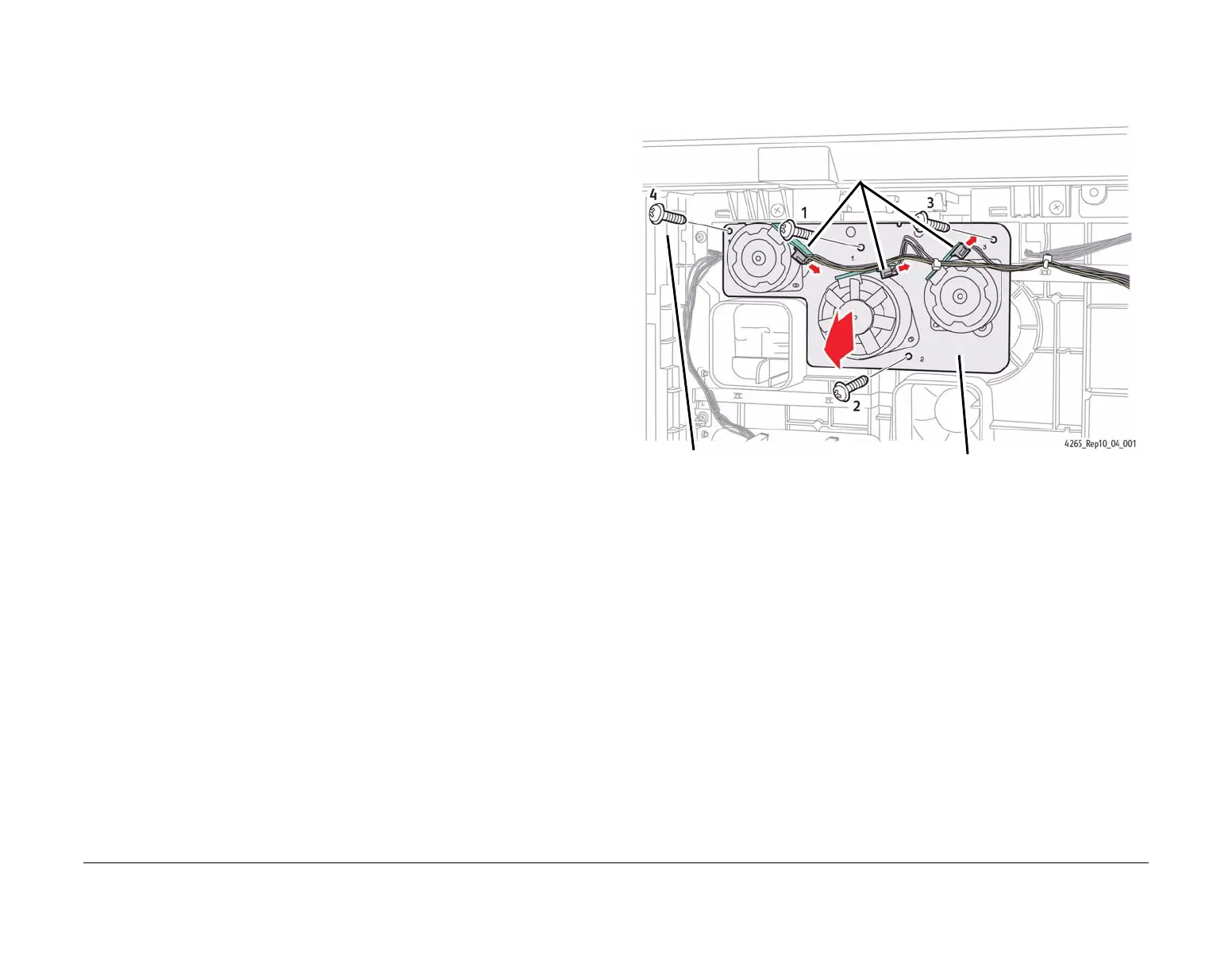
3. Remove the Exit Drive Assembly (Figure 1).
NOTE: The position of each screw is numbered 1 to 4 on the Mounting Plate. Remove the
screws in reverse numerical order.
Figure 1 Removing the Exit Drive Assembly
Replacement
NOTE: Reinstall the 4 screws that secure the exit drive assembly in numerical order.
1. Replacement is the reverse of the removal procedure.
1
Disconnect the three connectors.
2
Remove the four numbered mounting
screws in reverse order.
3
Remove the Exit
Drive Assembly.

 Loading...