January 2016
4-167
WorkCentre WorkCentre 4150/4250/4260WorkCentre 4150/4250/42604150/
REP 12.3
Repairs and Adjustments
REP 12.3 Transport Assembly Components
Parts List on PL 12.20
Purpose
This procedure is used to repair the following components:
NOTE: Only perform the steps that are necessary to repair the damaged component.
• Exit Sensor, PL 12.20 Item 7.
• Exit Roll, PL 12.20 Item 1.
• Drive belt, PL 12.20 Item 12.
• Paper Detector Sensor, PL 12.20 Item 25.
Removal
WARNING
Switch off the electricity to the machine. Disconnect the power cord from the customer
supply while performing tasks that do not need electricity. Electricity can cause death or
injury. Moving parts can cause injury.
WARNING
Take care during this procedure. Sharp edges may be present that can cause injury.
CAUTION
Before performing this procedure, refer to General Disassembly Precautions, GP 10.
1. Remove the Finisher, REP 12.1.
2. Remove the Finisher covers, REP 12.4.
3. Remove the Paddle Motor and bracket, PL 12.30 Item 5.
4. Remove the Exit Belt cover, PL 12.10 Item 20.
5. Remove the Exit Cover, PL 12.10 Item 6.
6. If necessary, remove the Exit Sensor, PL 12.20 Item 7.
7. Disconnect the Exit Sensor bulkhead connector. Remove the upper exit guide, PL 12.20
Item 2.
8. Remove the Lower Exit Guide, PL 12.20 Item 9.
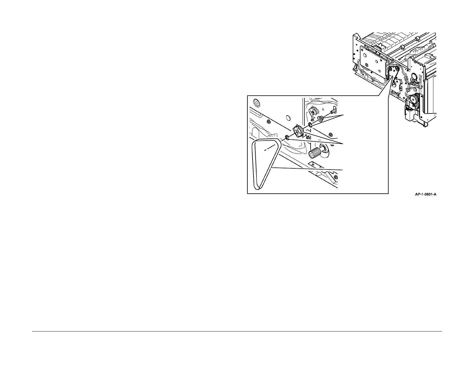
9. Prepare to remove the Exit Roll (Figure 1).
Figure 1 Preparing to Remove the Exit Roll
1
Remove the drive
belt.
2
Remove the E-clip
then the pulley.
3
Remove the E-clip
then the bearing.

 Loading...