January 2016
4-148
WorkCentre WorkCentre 4150/4250/4260WorkCentre 4150/4250/42604150/
REP 10.2
Repairs and Adjustments
REP 10.2 Exit Guide Assembly and Exit Assembly
Parts List on PL 10.10, PL 10.15
Removal
WARNING
Switch off the electricity to the machine. Disconnect the power cord from the customer
supply while performing tasks that do not need electricity. Electricity can cause death or
injury. Moving parts can cause injury.
WARNING
Take care during this procedure. Sharp edges may be present that can cause injury.
CAUTION
Before performing this procedure, refer to General Disassembly Precautions, GP 10.
1. Remove the DADF. Refer to (4150) REP 5.1 or (4250/4260/4265) REP 5.3.
2. Remove the scanner assembly, (4150) REP 14.1 or (4250/4260/4265) REP 14.3.
3. Open the side cover assembly, PL 7.30 Item 1.
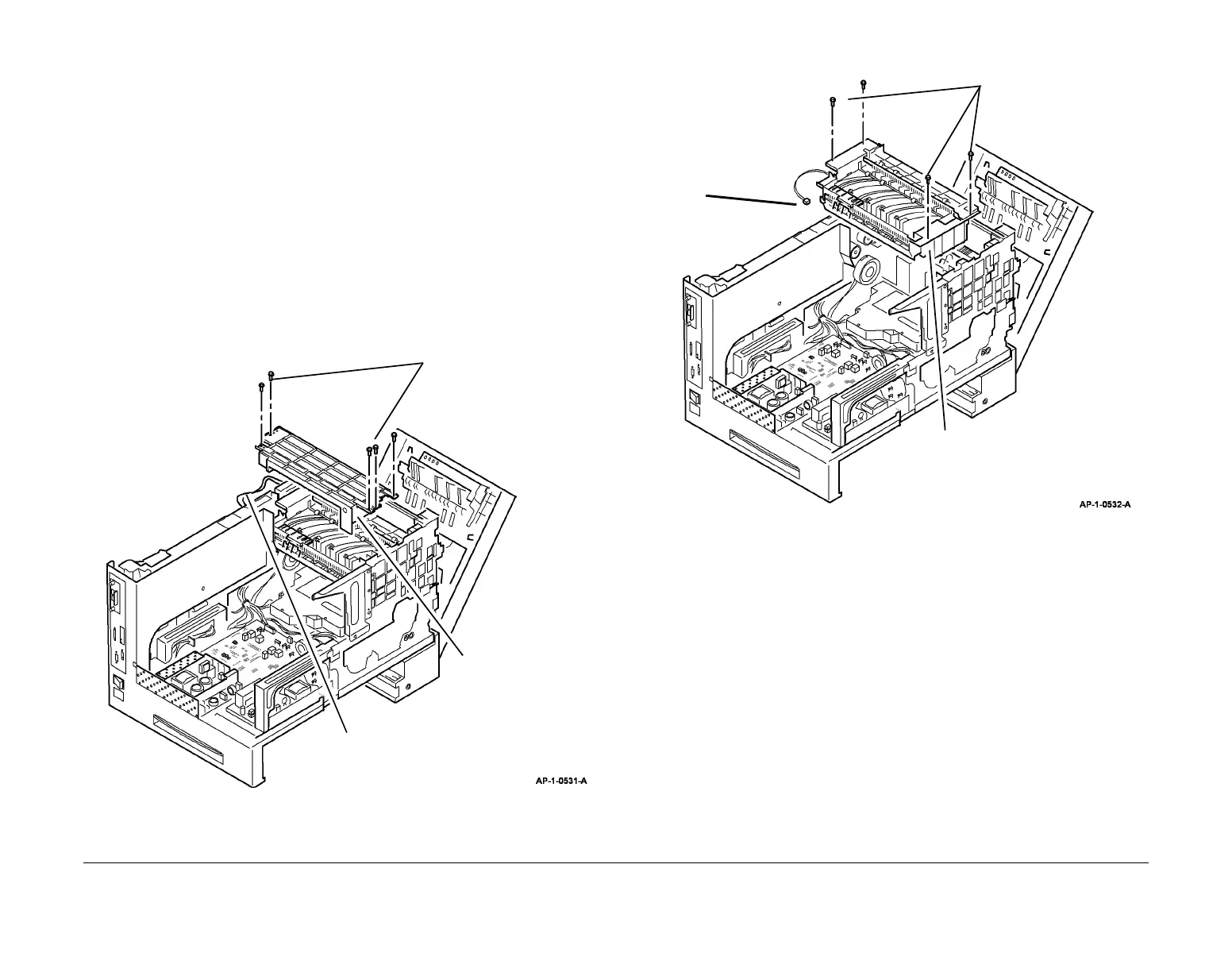
4. Remove the exit guide assembly, Figure 1.
Figure 1 Exit guide assembly removal
5. Remove the exit assembly, Figure 2.
Figure 2 Exit assembly removal
Replacement
Replacement is the reverse of the removal procedure.
1
Release the harness
from the plastic guides.
2
Remove 5 screws.
3
Remove the exit
guide assembly.
1
Disconnect (4150) CN6
or (4250/4260/4265)
CN8 and route the wire
harness back inside the
machine.
2
Remove 4 screws.
3
Remove the exit assembly.

 Loading...