January 2016
4-177
WorkCentre WorkCentre 4150/4250/4260WorkCentre 4150/4250/42604150/
REP 12.7, REP 12.8
Repairs and Adjustments
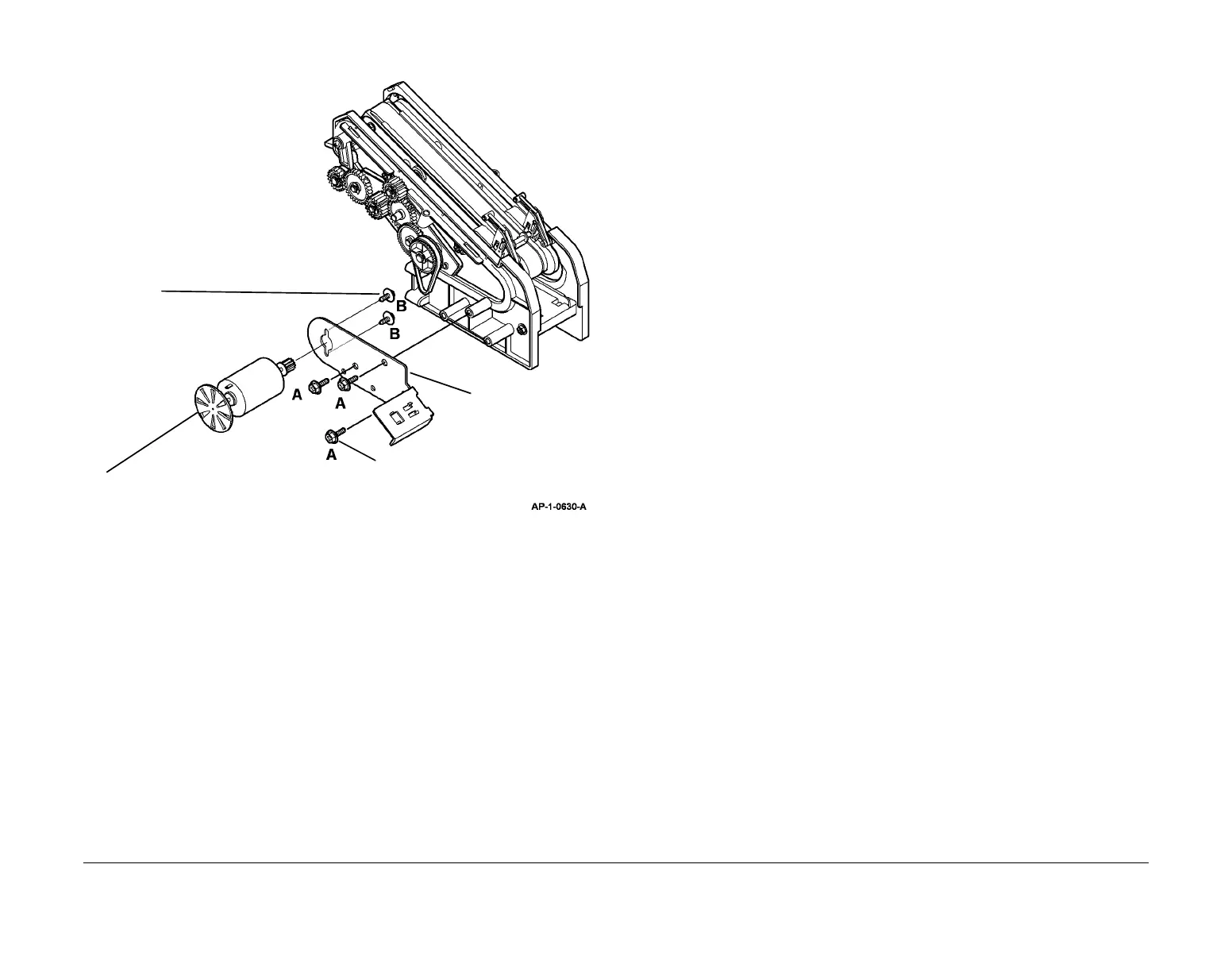
7. If necessary, remove the Ejector Motor (Figure 4).
Figure 4 Removing the Ejector Motor
Replacement
Replacement is the reverse of the removal procedure.
NOTE: Ensure that the front Support Finger and rear Support Finger are aligned correctly.
REP 12.8 Jogger Belts
Parts List on PL 12.30
Removal
WARNING
Switch off the electricity to the machine. Disconnect the power cord from the customer
supply while performing tasks that do not need electricity. Electricity can cause death or
injury. Moving parts can cause injury.
WARNING
Take care during this procedure. Sharp edges may be present that can cause injury.
CAUTION
Before performing this procedure, refer to General Disassembly Precautions, GP 10.
1. Remove the particular Jogger Assembly, REP 12.5.
2. Remove the motor spring, PL 12.30 Item 18.
3. Remove the Jogger Motor, PL 12.30 Item 20 and the Jogger Motor bracket, PL 12.30 Item
19 as a unit from the Jogger Assembly.
4. Release the Jogger Belt from the Belt Holder, PL 12.30 Item 22.
5. Remove the Jogger Belt, PL 12.30 Item 23.
Replacement
Replacement is the reverse of the removal procedure. Ensure that the Jogger Belt has been
tensioned correctly before the Jogger Motor securing screws are tightened.
1
Remove three screws
marked A.
2
Remove the Ejector
Motor assembly.
3
Remove two screws
marked B.
4
Remove the Ejector Motor.

 Loading...