5-28
5
5. Turn the engine start switch to ON, and
then measure the input voltage between
the terminals e and g.
6. Turn the engine start switch to OFF.
7. Install the main relay, and then install the
relay cover and fuse cover.
8. Install the intake manifold (STBD). See
“Installing the intake manifold” (6-18).
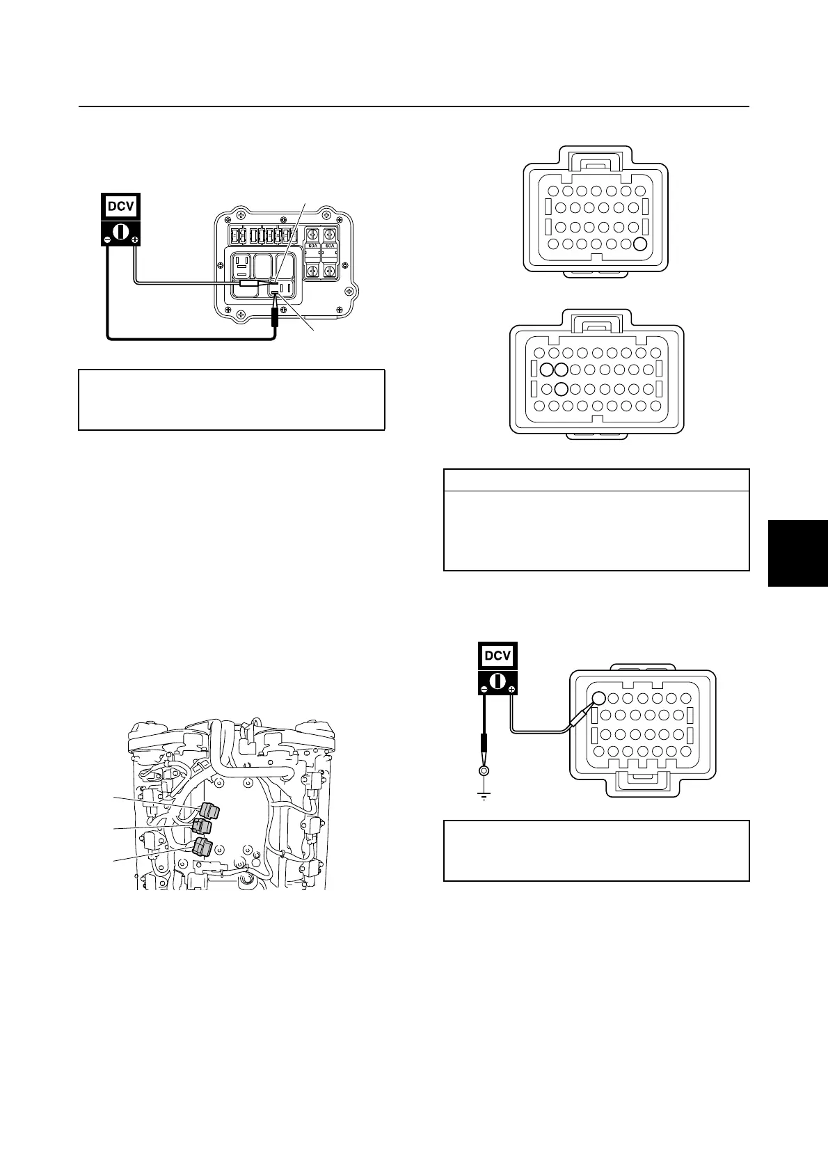
Checking the engine ECM circuit
1. Remove the engine ECM cover.
2. Remove the engine ECM, and then dis-
connect the engine ECM couplers a, b,
and c.
3. Check the wiring harness for continuity.
4. Measure the input voltage at the engine
ECM coupler a.
5. Remove the intake manifold (STBD).
See “Removing the intake manifold” (6-
17).
6. Remove the fuse holder 1, and then dis-
connect the fuse holder couplers d and
e.
Main relay input voltage:
Terminal e–Terminal g
12.0 V (battery voltage)
e
g
a
b
c
Wiring harness continuity:
b Terminal 46–Ground
c Terminal 68–Ground
c Terminal 69–Ground
c Terminal 76–Ground
Engine ECM input voltage:
a Terminal 7–Ground
12.0 V (battery voltage)
46
69 68
76
b
c
a
7
Checking the electrical component / Engine control system and component

 Loading...


