5-63
ELEC
Electrical system
15. Connect the shift cut switch coupler.
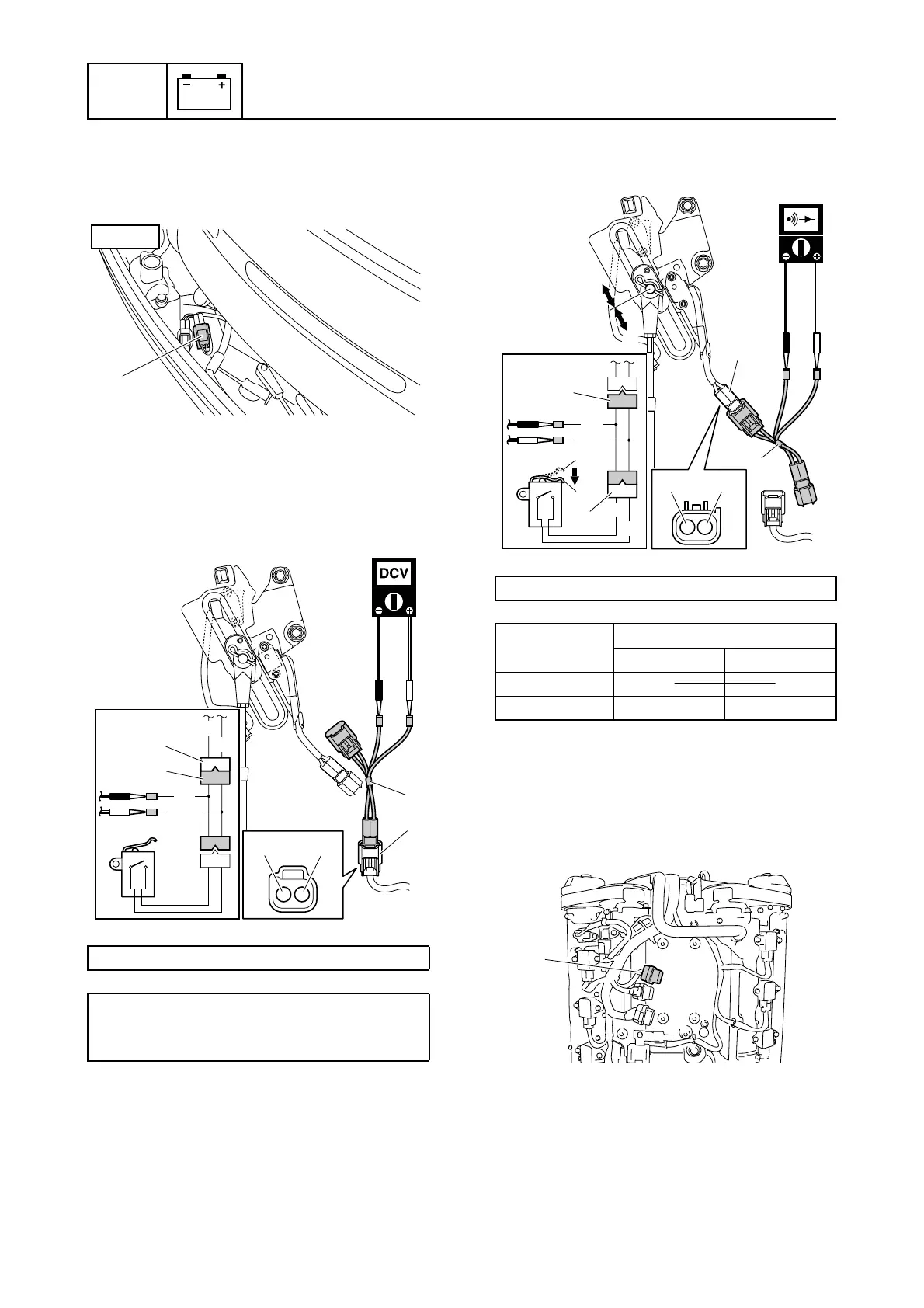
Checking the neutral switch
1. Disconnect the neutral switch coupler a.
2. Connect the special service tool 1 to the
neutral switch coupler a.
3. Turn the engine start switch to ON, and
then measure the input voltage.
4. Turn the engine start switch to OFF.
5. Disconnect the special service tool 1,
and then connect it to the neutral switch
coupler b.
6. Check the neutral switch for continuity.
Replace if out of specification.
7. Disconnect the special service tool.
8. Remove the engine ECM cover.
9. Remove the engine ECM, and then dis-
connect the engine ECM coupler e.
10. Check the wiring harness for continuity.
Test harness (2 pins) 1: 90890-06867
Neutral switch input voltage:
Blue/Green (L/G)–Black (B)
4.75–5.25 V
a
STBD
G/W
G
B
L/G
a
a
1
1
L/GB
Test harness (2 pins) 1: 90890-06867
Switch
position
Lead color
L/G B
Pushed c C
CC
CC
CC
C
Free d
G/W
G
B
L/G
1
1
b
b
c
d
c
d
d
L/G B
e

 Loading...


