5-31
ELEC
Electrical system
4. Turn the engine start switch to OFF.
5. Remove the engine ECM cover.
6. Remove the engine ECM, and then dis-
connect the engine ECM coupler b.
7. Check the wiring harness for continuity.
8. Connect the engine ECM coupler.
NOTICE: Make sure that the rubber
seal is installed properly in the engine
ECM coupler.
9. Install the engine ECM, and then tighten
the engine ECM bolts to the specified
torque.
10. Install the engine ECM cover.
11. Connect the APS coupler.
12. Install the intake manifold (STBD). See
“Installing the intake manifold” (6-18).
Checking the ETV and TPS
TPS 1 and TPS 2 are components of the
ETV, which cannot be disassembled.
Do not loosen the throttle stop screw nut
or turn the throttle stop screw.
1. Start the engine, warm it up for 5–10 min-
utes, and then stop it.
2. Connect the YDIS to display “Throttle
position sensor 1,” “Throttle valve open-
ing,” and “Throttle position sensor 2.”
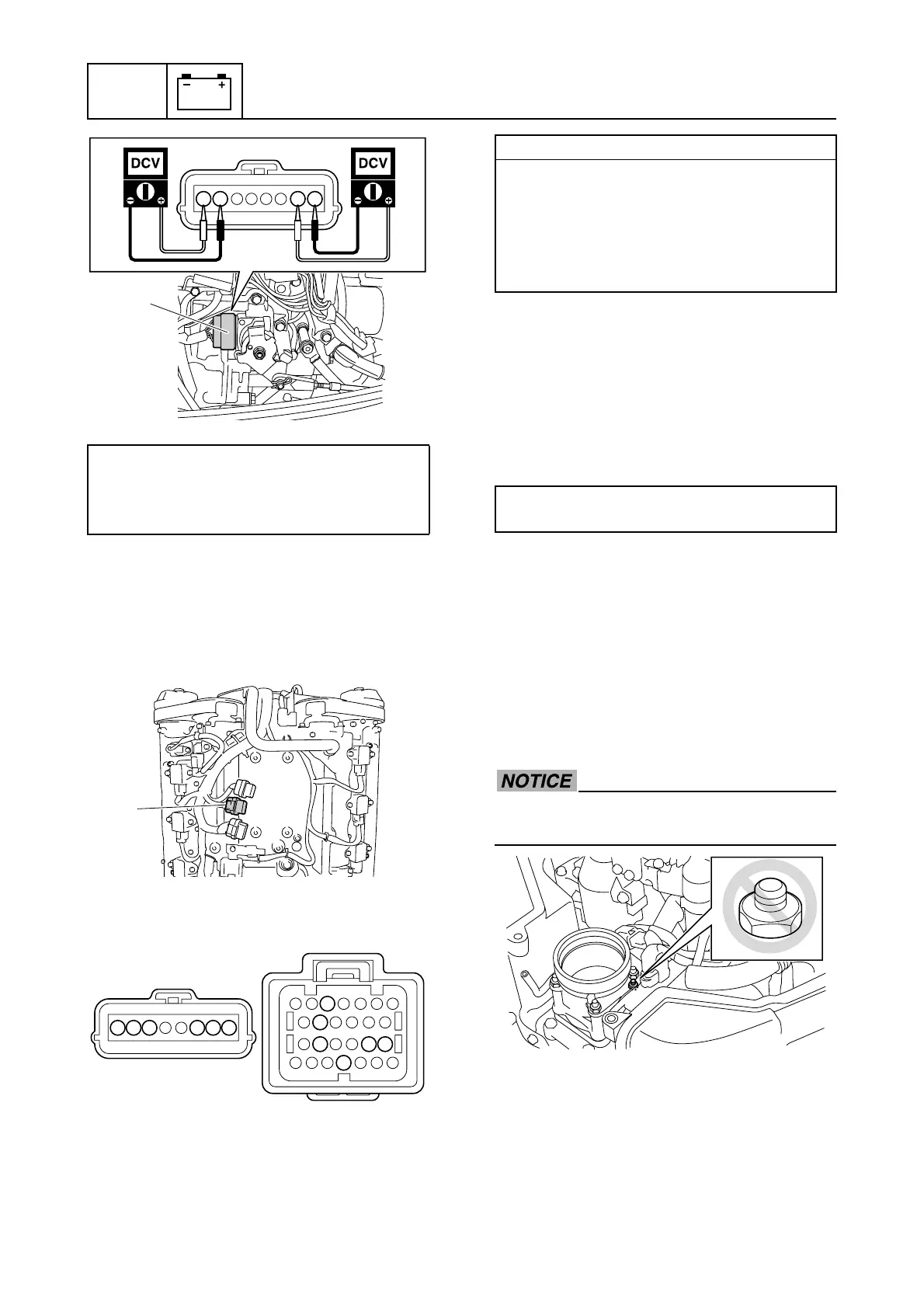
APS input voltage:
Terminal 2–Terminal 1
Terminal 8–Terminal 7
4.75–5.25 V
1278
a
a
b
31
38
44
49
41 40
12
36
7
8
ab
Wiring harness continuity:
a Terminal 1–b Terminal 40
a Terminal 2–b Terminal 44
a Terminal 3–b Terminal 38
a Terminal 6–b Terminal 31
a Terminal 7–b Terminal 41
a Terminal 8–b Terminal 49
Engine ECM bolt:
7 N·m (0.7 kgf·m, 5.2 ft·lb)

 Loading...


