7-20
7
Removing the wiring harness
When removing the wiring harness and wir-
ing harness guide, the fuel line must be dis-
connected. Therefore, make sure to reduce
the fuel pressure before performing the dis-
assembly procedure.
1. Disconnect the air temperature sensor
coupler, and then remove the blowby
hose and intake silencer. See “Removing
the intake silencer” (6-17).
2. Remove the intake manifold (PORT).
See “Removing the intake manifold” (6-
17).
3. Disconnect the quick connectors. See
steps 3–5 in “Disconnecting the quick
connector” (6-7).
4. Remove the fuel hoses and fuel rail cov-
ers. See steps 2 and 3 in “Removing the
fuel injector” (6-45).
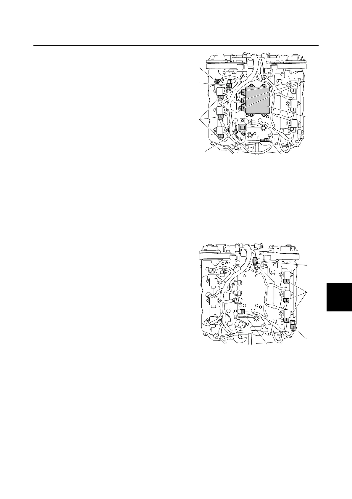
5. Remove the engine ECM 1, and then
disconnect the engine ECM couplers a.
6. Disconnect the cam position sensor cou-
pler (PORT IN) b, cam position sensor
coupler (PORT EX) c, and ignition coil
couplers (PORT) d.
7. Remove the knock sensor coupler e
from the engine ECM bracket, and then
disconnect the knock sensor coupler.
8. Remove joint coupler 2 f from the
bracket.
9. Remove the air-fuel sensor coupler g
from the bracket.
10. Remove joint coupler 1 h from the wiring
harness guide.
11. Disconnect the ignition coil couplers
(STBD) k and cam position sensor cou-
pler (STBD IN) m.
12. Remove the water pressure sensor cou-
pler n from the bracket.
13. Remove the cam position sensor lead
(PORT IN) from the holder 2.
14. Remove the plastic ties 3.
15. Remove the holders p on the wiring har-
ness from the engine ECM bracket.
16. Remove the wiring harness 4 from the
holders 5, 6, and 7 on the engine
ECM bracket.
b
c
d
e
f
g
1
a
n
k
h
m
Wiring harness

 Loading...


