5-44
5
10. Connect the engine ECM coupler.
NOTICE: Make sure that the rubber
seal is installed properly in the engine
ECM coupler.
11. Install the engine ECM, and then tighten
the engine ECM bolts to the specified
torque.
12. Install the engine ECM cover.
13. Connect the water direction switch cou-
pler.
Checking the fuel injector
1. Check the operation of the fuel injectors
using the YDIS “Stationary test” and
check the operating sound. See “Func-
tion” (4-2).
2. Remove the fuel rail covers, and then
disconnect the fuel injector couplers a.
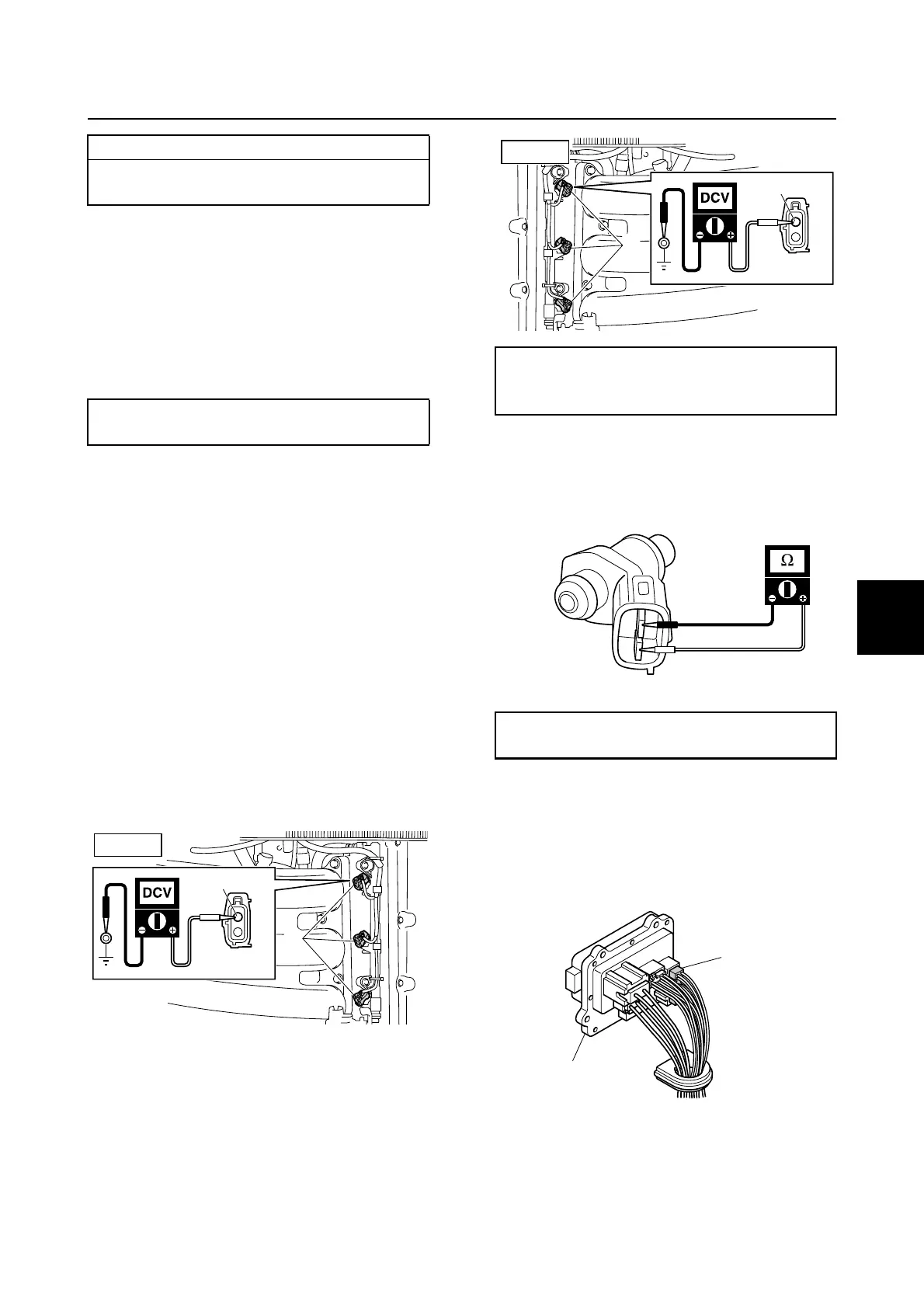
3. Turn the engine start switch to ON, and
then measure the input voltage at the
fuel injector coupler.
4. Turn the engine start switch to OFF.
5. Measure the fuel injector resistance.
6. Remove the intake manifold (STBD).
See “Removing the intake manifold” (6-
17).
7. Remove the fuse holder 1, and then dis-
connect the fuse holder coupler b.
8. Remove the engine ECM cover.
9. Remove the engine ECM, and then dis-
connect the engine ECM coupler c.
Wiring harness continuity:
a Terminal 1–e Terminal 5
a Terminal 2–e Terminal 18
Engine ECM bolt:
7 N·m (0.7 kgf·m, 5.2 ft·lb)
R/Y
PORT
a
Fuel injector input voltage:
Red/Yellow (R/Y)–Ground
12.0 V (battery voltage)
Fuel injector resistance (reference data):
12.0 Ω at 20 °C (68 °F)
R/Y
STBD
a
1
b
Engine control system and component / Fuel control unit and component

 Loading...


