5-32
5
3. Turn the engine start switch to ON, and
then measure the TPS output voltages
and throttle valve opening angles when
the remote control lever is at the fully
closed position a and fully open position
b.
TIP:
The actual TPS output voltage and throttle
valve opening angle may vary according to
environmental conditions and engine temper-
ature.
4. Turn the engine start switch to OFF.
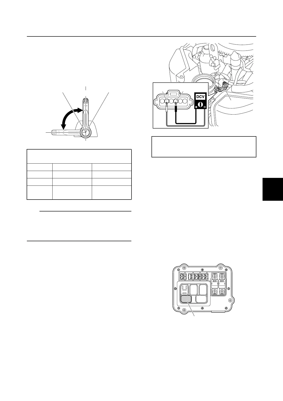
5. Remove the intake silencer, and then
disconnect the ETV coupler c. See
“Removing the intake silencer” (6-17).
6. Turn the engine start switch to ON, and
then measure the TPS input voltage at
the ETV coupler. Check the wiring har-
ness if out of specification. See “Check-
ing the ETV and TPS circuit” (5-33).
7. Turn the engine start switch to OFF.
8. Connect the ETV coupler, and then
install the intake silencer. See “Installing
the intake silencer” (6-19).
Checking the ETV motor relay
1. Remove the intake manifold (STBD).
See “Removing the intake manifold” (6-
17).
2. Remove the fuse cover and relay cover,
and then remove the ETV motor relay 1.
NOTICE: Be careful not to damage the
relay.
3. Check the ETV motor relay. See step 3 in
“Checking the main relay” (5-27).
4. Measure the input voltage between the
terminal a and ground, and the terminal
b and ground.
TPS output voltage and throttle valve
opening angle (reference data):
Item Fully closed a Fully open b
TPS 1 0.500–0.700 —
TPS 2 — 4.600–4.700
Opening
angle
5.1° 84.4°
N
F
N
R
b
a
TPS input voltage:
Orange (O)–Black (B)
4.75–5.25 V
B
O
c
1
Engine control system and component
 Loading...