3-11
RIG
GING
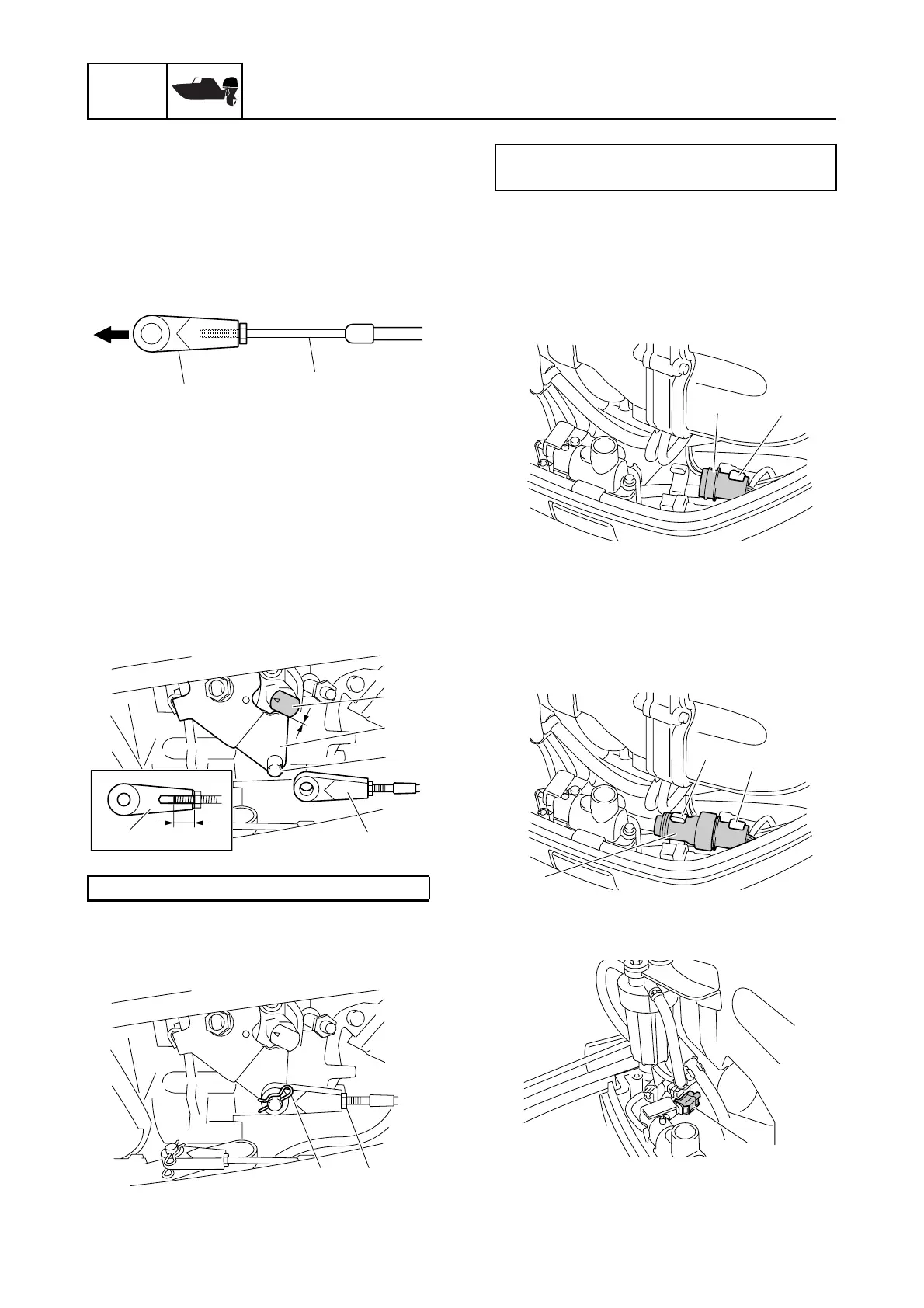
Rigging information
16. Fully screw in the throttle cable joint B to
the throttle cable A.
17. Pull the inner cable so that there is no
free play (backlash).
18. Check that the accelerator lever n con-
tacts the stopper p.
19. Adjust the throttle cable joint B, and then
connect the throttle cable joint B to the
pin r of the accelerator lever n.
WARNING! The throttle cable joint
must be screwed in 8.0 mm (0.31 in) or
more.
20. Install the clip C, and then tighten the
throttle cable locknut D to the specified
torque.
21. Check the shift cable and throttle cable
for proper operation.
Installing the wiring harness
1. Remove the 10-pin coupler a from the
holder b on the bracket.
2. Route the extension wiring harness
through the bottom cowling.
3. Connect the 10-pin coupler c, and then
fasten it using the holders b and d on
the bracket.
Installing the isolator lead (optional)
1. Remove the cap 1.
2. Route the isolator lead 2 through the
bottom cowling.
Dimension s: 8.0 mm (0.31 in) or more
A
B
B
s
p
n
r
B
DC
Throttle cable locknut D:
4 N·m (0.4 kgf·m, 3.0 ft·lb)
b
a
d
b
c
1

 Loading...


