0-4
0
How to use this manual
Manual format
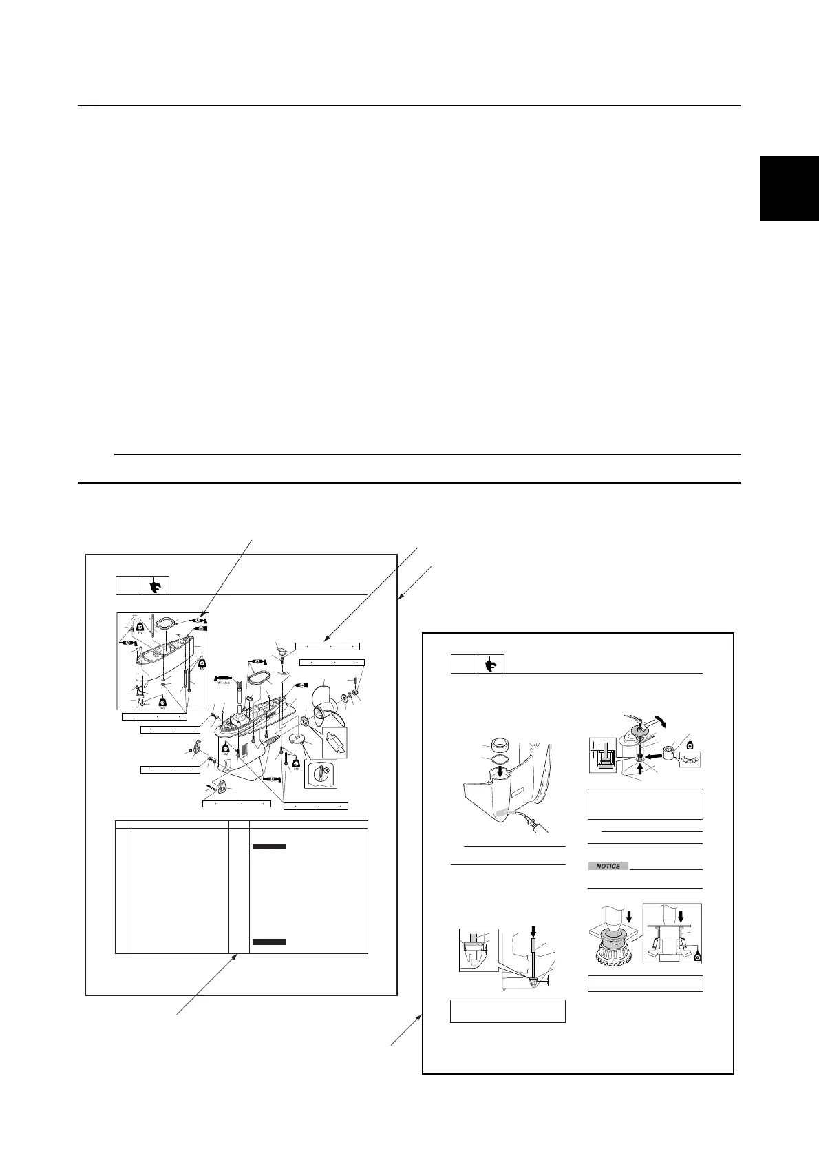
The format of this manual has been designed to make service procedures clear and easy to under-
stand. Use the following information as a guide for effective and quality service.
• Parts are shown and detailed in an exploded diagram and are listed in the component list (see 1
in the following figure for an example page).
• The component list consists of part names and quantities, as well as bolt and screw dimensions
(see 2 in the following figure).
• Symbols are used to indicate important aspects of a procedure, such as the grade of lubricant and
the lubrication points (see 3 in the following figure).
• Tightening torque specifications are provided in the exploded diagrams (see 4 in the following fig-
ure), and in the related detailed instructions. Some torque specifications are listed in stages as
torque figures or angles in degrees.
• Separate procedures and illustrations are used to explain the details of removal, checking, and
installation where necessary (see 5 in the following figure for an example page).
TIP:
For troubleshooting procedures, see Chapter 4, “Troubleshooting.”
8-1
LOWR
Lower unit
Lower unit (regular rotation model)
È U-transom model
No. Part name Q’ty Remarks
1 Water inlet cover (PORT) 1
2 Bolt 1 M5 40 mm
3Gasket 2
Not reusable
4 Drain screw 1
5 Water inlet cover (STBD) 1
6 Self-locking nut 1
7 Check screw 1
8Dowel 2
9Plate 1
10 Rubber seal 1
11 Bolt 1 M10 45 mm
12 Grommet 1
13 Lower unit 1
14 Spacer 1
15 Propeller 1
16 Cotter pin 1
Not reusable
17 Propeller nut 1
14
20
22
1
2
22
13
15
18
16
19
17
22
21
11
12
25
26
24
6
3
7
8
9
10
8
5
4
3
23
34
33
32
31
30
29
25
35
27
28
42 N m (4.2 kgf m, 31.0 ft lb)
54 N
m (5.4 kgf m, 39.8 ft lb)
47 N
m (4.7 kgf m, 34.7 ft lb)
9 N
m (0.9 kgf m, 6.6 ft lb)
9 N m (0.9 kgf m, 6.6 ft lb)
2.3 N
m (0.23 kgf m, 1.70 ft lb)
47 N
m (4.7 kgf m, 34.7 ft lb)
È
8-19
LOWR
Lower unit
2. Heat the installation area of the taper
roller bearing outer race in the lower case
with a gas torch, and then install the
outer race 2.
NOTICE:
When heating
the lower case, heat the entire
installation area evenly. Otherwise,
the paint on the lower case could be
burned.
TIP:
Do not reuse a shim if it is any deformed or
scratched.
3. While holding the special service tool 3,
strike the tool to check that the taper
roller bearing outer race is installed
properly. If a high-pitched metallic sound
is produced when the special service tool
is struck, the outer race is installed
properly.
4. Install the rollers into the needle bearing
outer race, and install the special service
tool into the needle bearing assembly 5,
and then install the needle bearing
assembly 5.
TIP:
The needle bearing contains 28 rollers.
Assembling the forward gear
Do not reuse the bearing, always replace
it with a new one.
1. Install a new taper roller bearing.
Driver rod LL 3: 90890-06605
Bearing outer race attachment 4:
90890-06658
1
2
3
3
4
4
Ball bearing attachment 6:
90890-06655
Bearing outer race puller assembly 7:
90890-06523
Bearing inner race attachment 1:
90890-06659
6
7
5
1
x
x
5
2
3
4
1
Safety while working / How to use this manual

 Loading...


