5-33
ELEC
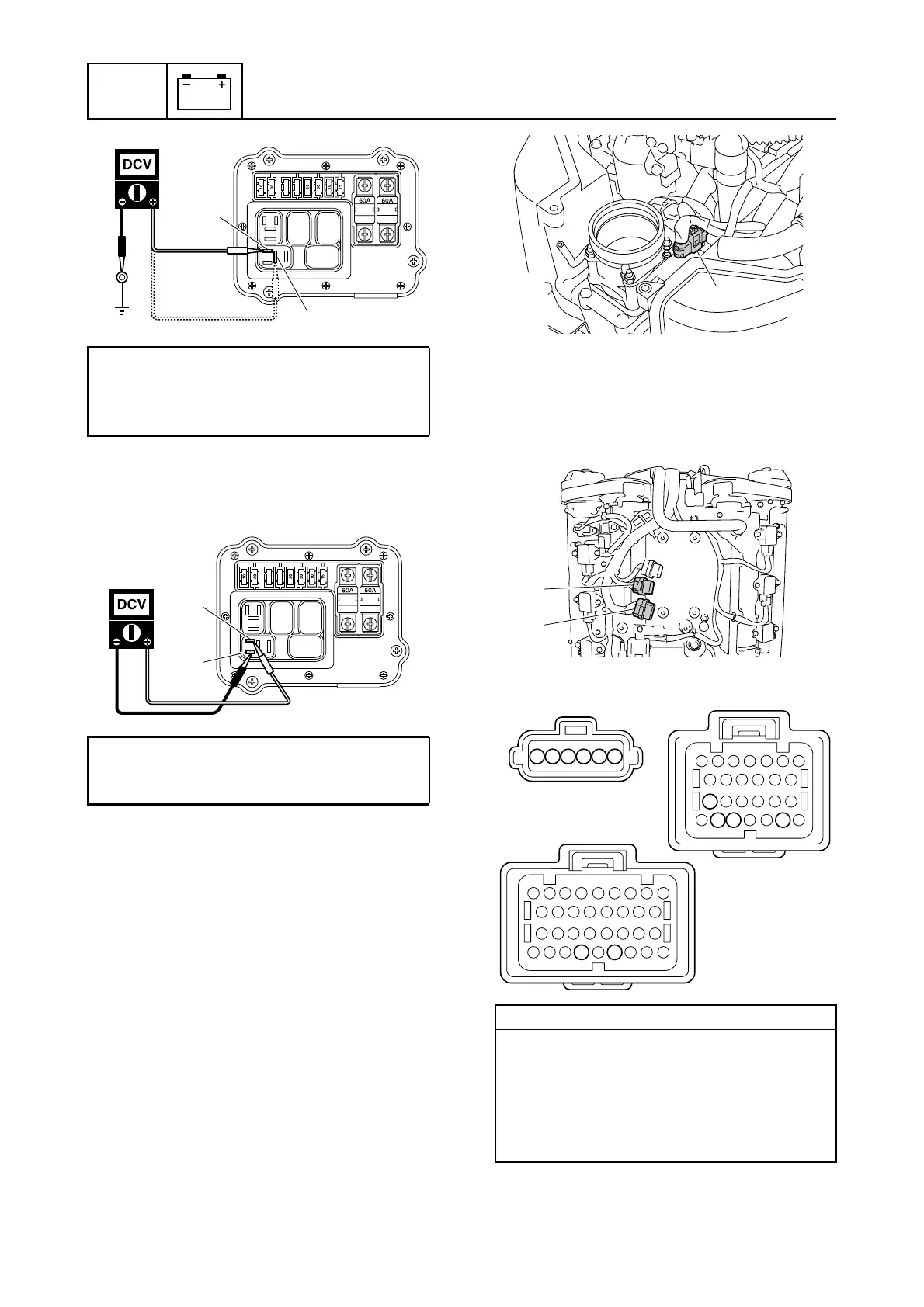
Electrical system
5. Turn the engine start switch to ON, and
then measure the input voltage between
the terminals a and c.
6. Turn the engine start switch to OFF.
7. Install the ETV motor relay, and then
install the relay cover and fuse cover.
8. Install the intake manifold (STBD). See
“Installing the intake manifold” (6-18).
Checking the ETV and TPS circuit
1. Remove the intake silencer. See
“Removing the intake silencer” (6-17).
2. Disconnect the ETV coupler a.
3. Remove the engine ECM cover.
4. Remove the engine ECM, and then dis-
connect the engine ECM couplers b and
c.
5. Check the wiring harness for continuity.
6. Connect the ETV coupler.
ETV motor relay input voltage:
Terminal a–Ground
Terminal b–Ground
12.0 V (battery voltage)
ETV motor relay input voltage:
Terminal a–Terminal c
12.0 V (battery voltage)
b
a
a
c
Wiring harness continuity:
a Terminal 1–c Terminal 83
a Terminal 2–c Terminal 81
a Terminal 3–b Terminal 47
a Terminal 4–b Terminal 45
a Terminal 5–b Terminal 51
a Terminal 6–b Terminal 50
a
b
c
123456
a
c
b
45
51 50 47
83 81

 Loading...


