7-58
7
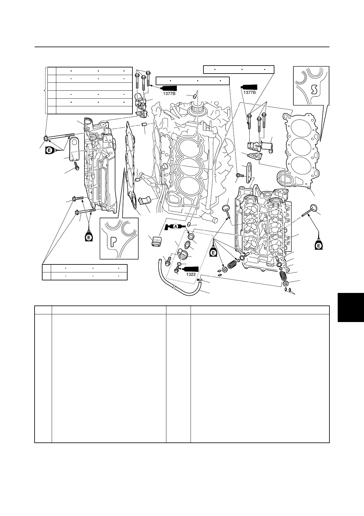
Cylinder head
È Only the tightening torques for new cylinder head bolts are shown in the exploded diagram. For
the tightening torques when reusing the cylinder head bolts, see “Installing the cylinder head”
(7-68).
(*1): Loosen completely
No. Part name Q’ty Remarks
1Bolt 6 M6 × 35 mm
2OCV 2
3 Filter 2 39
3939
39
4 Engine hanger (PORT) 1
5Bolt 6 M6 × 18 mm
6 Gasket (PORT) 1 39
3939
39
7 Dowel 4
8 Gasket (STBD) 1 39
3939
39
9 Engine hanger (STBD) 1
10 Cylinder head (STBD) 1
11 Exhaust valve 12
12 Hose 1
13 Clip 1
14 Valve guide 24 39
3939
39
15 Valve spring retainer 24
1
2
14 N m (1.4 kgf m, 10.3 ft lb)
28 N
m (2.8 kgf m, 20.7 ft lb)
1
1
2
2
3
3
4
5
5
6
7
7
8
9
10
11
12
13
14
15
16
17
18
20
23
24
27
28
31
29
30
19
25
26
22
21
7
7
12 N m (1.2 kgf m, 8.9 ft lb)
32
32
1
2
30 N m (3.0 kgf m, 22.1 ft lb)
60 N
m (6.0 kgf m, 44.3 ft lb)
3
4
(* 1)
30 N m (3.0 kgf m, 22.1 ft lb)
5
6
60 N m (6.0 kgf m, 44.3 ft lb)
90˚
7 N m( 0.7 kgf m, 5.2 ft lb)
È
Exhaust cover / Cylinder head

 Loading...


