7-64
7
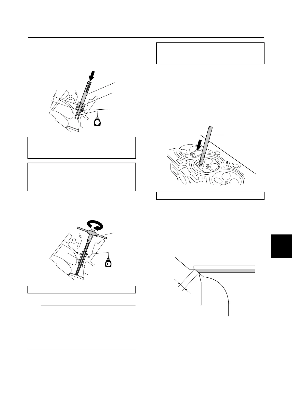
2. Install a new valve guide 3 using the
special service tools 2 from the cam-
shaft side until the valve guide installer
4 to the specified height a.
3. Insert the special service tool 5 into the
valve guide 3, and then ream the valve
guide.
TIP:
• Turn the special service tool 5 clockwise to
ream the valve guide.
• Do not turn the reamer counterclockwise
when removing the reamer.
• Make sure to clean the valve guide after
reaming it.
4. Measure the valve guide inside diameter.
Checking the valve seat
1. Eliminate carbon deposits from the valve.
2. Apply a thin, even layer of Mechanic’s
blueing dye (Dykem) onto the valve seat.
3. Lap the valve slowly on the valve seat
with a special service tool 1.
4. Measure the valve seat contact width a
where the blueing dye is adhered to the
valve face. Reface the valve seat if the
valve is not seated properly or if the valve
seat contact width is out of specification.
Replace the valve guide if the valve seat
contact width is uneven.
Valve guide remover/installer 2:
90890-06801
Valve guide installer 4: 90890-06810
Valve guide installation height a:
Intake and exhaust:
12.500–12.900 mm (0.4921–0.5079
in)
Valve guide reamer 5: 90890-06804
E
2
3
4
a
3
5
Valve guide inside diameter:
Intake and exhaust:
5.504–5.522 mm (0.2167–0.2174 in)
Valve lapper 1: 90890-04101
1
a
Cylinder head

 Loading...


