2-21
TECH
FEA
Technical features and description
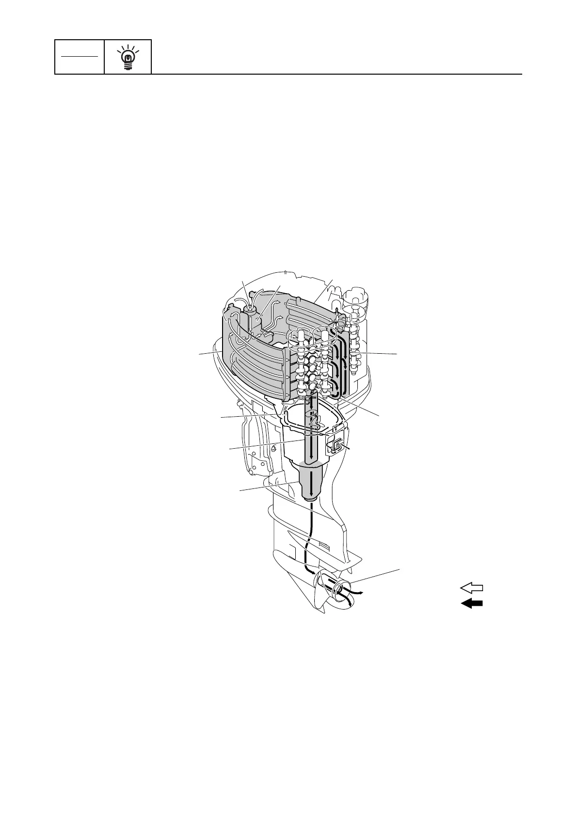
Intake and exhaust system
The single electronic throttle valve, which is operated by the engine ECM, enables precise control of
the intake air. The intake air is smoothly routed into each combustion chamber through the surge
tanks and the long intake manifolds for greater power. The long intake manifolds are designed to
increase air flow, thereby boosting low and mid-range torque and resulting in quicker acceleration.
The intake system has adopted intake valves with large diameter valve heads to increase the charg-
ing efficiency of the intake air.
The exhaust gases are cooled with water as they pass through the in-bank exhaust system. For
increased performance, the gases are smoothly vented straight down and out through the propeller.
The exhaust gas passages are anodized to protect the lower unit from corrosion.
Intake and exhaust diagram
È Intake air flow
É Exhaust gas flow
1 Throttle body
2 Surge tank
3 Intake manifold
4 Exhaust cover
5 Exhaust guide
6 Exhaust manifold
7 Muffler
8 Propeller
É
È
1
2
3
3
4
5
6
7
8
4

 Loading...


