5-50
5
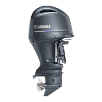
21. Disconnect the special service tool.
22. Install the vapor shut-off valve to the
throttle body assembly.
23. Install the throttle body assembly. See
“Installing the throttle body assembly” (6-
24).
24. Install the intake manifolds. See “Install-
ing the intake manifold” (6-18).
25. Install the intake silencer. See “Installing
the intake silencer” (6-19).
Charging unit and component
Checking the lighting coil
1. Remove the intake manifold (STBD).
See “Removing the intake manifold” (6-
17).
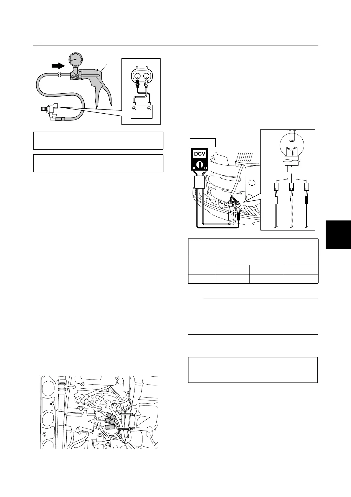
2. Remove the stator assembly leads from
the plastic ties 1, and then disconnect
the stator assembly couplers a.
3. Move the stator assembly leads away
from the area covered by the intake man-
ifold, and then install the intake manifold
(STBD). See “Installing the intake mani-
fold” (6-18).
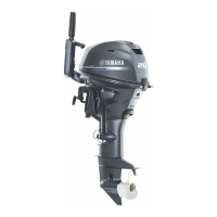
4. Measure the lighting coil output peak
voltage between all combinations of the
terminals.
TIP:
When measuring the output peak voltage
under the cranking condition, remove the clip
from the engine shut-off switch to prevent the
engine from starting.
5. Measure the lighting coil resistance.
6. Remove the intake manifold (STBD).
See “Removing the intake manifold” (6-
17).
7. Connect the stator assembly couplers,
and then fasten the stator assembly
leads using the plastic ties.
Vacuum/pressure pump gauge set 2:
90890-06756
Specified negative pressure:
67.0 kPa (0.67 kgf/cm
2
, 9.7 psi)
2
a
1
Lighting coil output peak voltage:
Green (G)–Green (G)
r/min
Unloaded
Cranking 1500 3500
DC V 8.3 44.7 97.7
Lighting coil resistance (reference data):
Green (G)–Green (G)
0.11–0.17 Ω at 20 °C (68 °F)
GG
G
STBD
Fuel control unit and component / Charging unit and component
 Loading...