5-75
ELEC
Electrical system
7. Connect the positive battery lead to the
connector f, connect the negative bat-
tery lead to the terminal b, and then
check the PTT relay for continuity.
Replace if out of specification.
8. Disconnect the special service tool.
9. Install the PTT relay.
10. Connect the PTT relay leads and PTT
relay coupler, and then tighten the PTT
relay terminal bolts and PTT relay termi-
nal nuts to the specified torque.
11. Install the intake manifold (STBD). See
“Installing the intake manifold” (6-18).
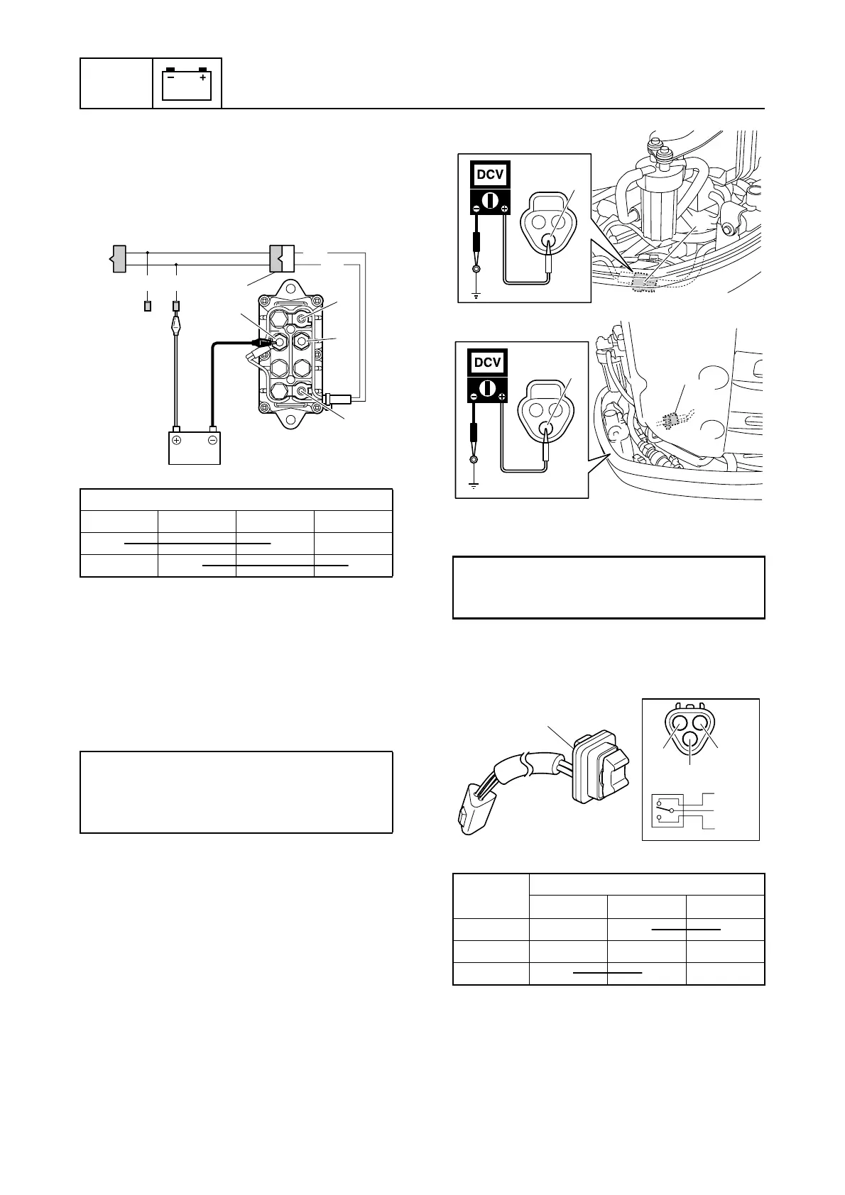
Checking the PTT switch (bottom
cowling)
1. Disconnect the PTT switch coupler a.
2. Measure the input voltage at the PTT
switch coupler.
È Regular rotation model
É Counter rotation model
3. Check the PTT switch 1 for continuity.
Replace if out of specification.
4. Remove the intake manifold (STBD).
See “Removing the intake manifold” (6-
17).
PTT relay continuity:
a b cd
C
CC
CC
CC
C
C
CC
CC
CC
C
PTT relay terminal bolt:
4 N·m (0.4 kgf·m, 3.0 ft·lb)
PTT relay terminal nut:
4 N·m (0.4 kgf·m, 3.0 ft·lb)
Lg
Sb
1
ef
d
c
a
b
GG/W
PTT switch input voltage:
Red (R)–Ground
12.0 V (battery voltage)
Switch
position
Terminal
b c d
UP C
CC
CC
CC
C
Free
DN C
CC
CC
CC
C
a
R
È
R
a
É
c
d
b
Lg
R
Sb
c
d
b
1

 Loading...


