5-43
ELEC
Electrical system
12. Connect the speed sensor coupler.
13. Install the engine ECM cover.
Fuel control unit and component
Checking the water detection switch
1. Disconnect the water detection switch
coupler a.
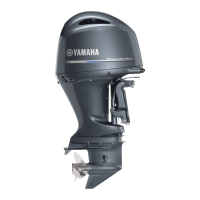
2. Turn the engine start switch to ON, and
then measure the input voltage at the
water detection switch coupler.
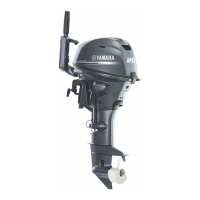
3. Turn the engine start switch to OFF, and
then remove the fuel cup assembly.
4. Check that the float 1 moves smoothly.
5. Check the water detection switch for con-
tinuity when the float 1 positions È and
É. NOTICE: Make sure not to remove
the clip 2 and float 1.
6. Install the fuel cup assembly. See step 2
in “Assembling the fuel filter assembly”
(6-14).
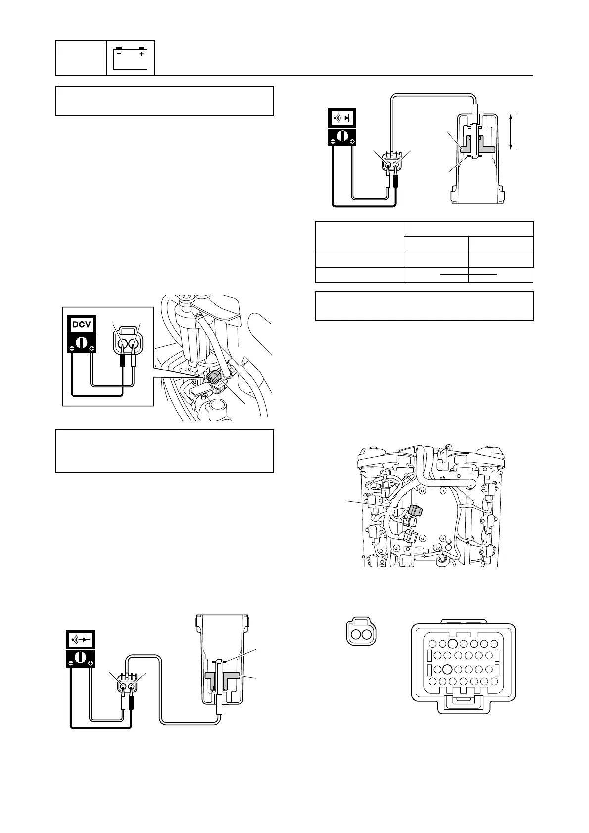
7. Remove the engine ECM cover.
8. Remove the engine ECM, and then dis-
connect the engine ECM coupler e.
9. Check the wiring harness for continuity.
Engine ECM bolt:
7 N·m (0.7 kgf·m, 5.2 ft·lb)
Water detection switch input voltage:
Blue/White (L/W)–Black (B)
4.75–5.25 V
a
L/W
B
b
2
1
c
È
Float position
Terminal
b c
È
É C
CC
CC
CC
C
Float height d (reference data):
40.0 mm (1.57 in)
1
2
d
cb
É
e
ae
1
2
5
18

 Loading...