7-33
POWR
Power unit
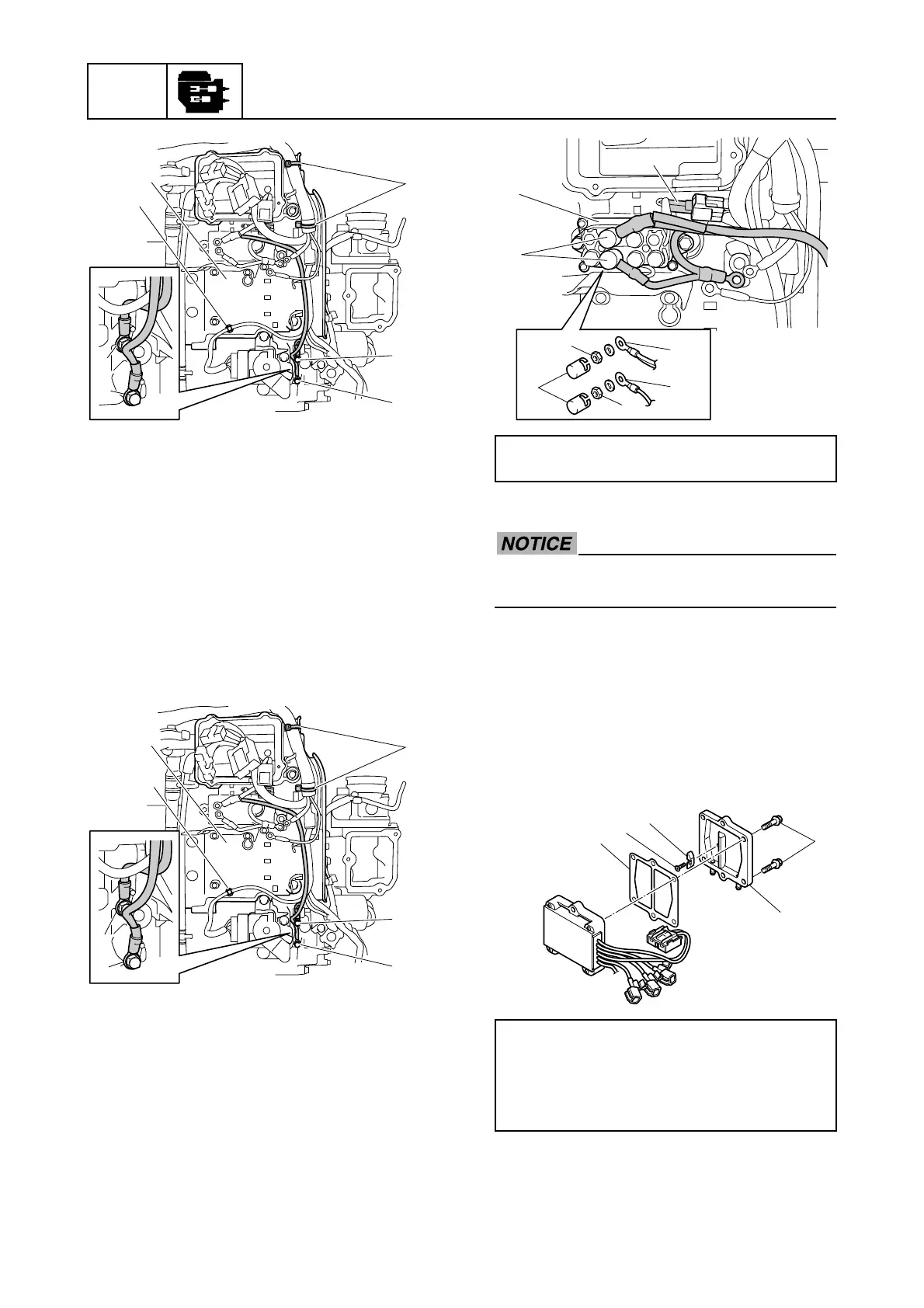
Installing the junction box
1. Install the junction box 1.
2. Install the holder a on the wiring har-
ness to the junction box 1.
3. Fasten the wiring harness using the plas-
tic ties 2.
4. Install the ground lead terminal b and
junction box wiring harness extension
terminal c.
5. Install the PTT relay 3.
6. Connect the PTT relay coupler d.
7. Connect the PTT relay terminals e, and
then tighten the PTT relay terminal nuts
4 to the specified torque.
8. Install the caps 5.
Installing the Rectifier Regulator
Do not reuse a gasket, always replace it
with a new one.
1. Install the anode 1 to the cover 2, and
then tighten the anode screw 3 to the
specified torque.
2. Install the gasket 4 and cover 2 to the
Rectifier Regulator, and then tighten the
Rectifier Regulator cover bolts 5 to the
specified torques in 2 stages.
3. Install the Rectifier Regulator 6, and
then tighten the Rectifier Regulator bolts
7 to the specified torques in 2 stages.
3
d
c
e
c
d
4
2
c
b
c
b
1
a
PTT relay terminal nut 4:
4 N·m (0.4 kgf·m, 3.0 ft·lb)
Anode screw 3:
3 N·m (0.3 kgf·m, 2.2 ft·lb)
Rectifier Regulator cover bolt 5:
1st: 6 N·m (0.6 kgf·m, 4.4 ft·lb)
2nd: 12 N·m (1.2 kgf·m, 8.9 ft·lb)
d
5
3
4
e
e
4
5
4
1
2
3
5

 Loading...


