5-29
ELEC
Electrical system
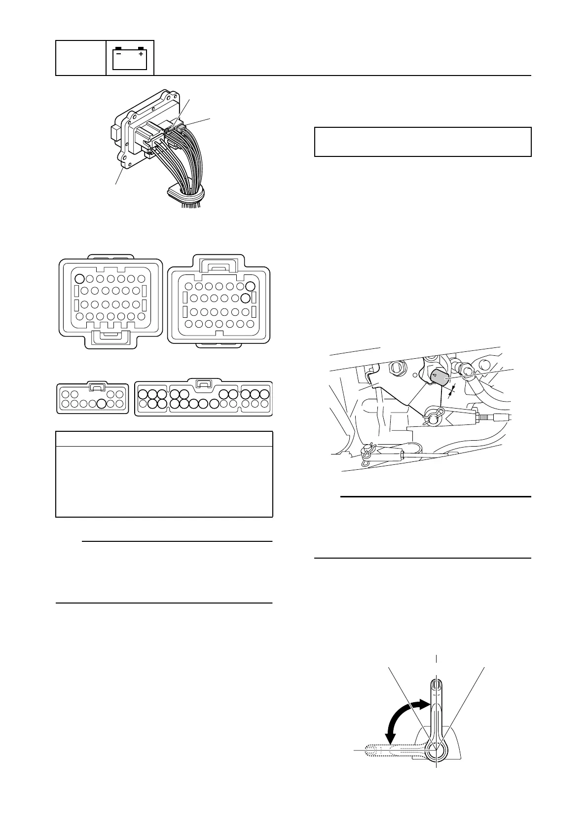
7. Check the wiring harness for continuity.
TIP:
Make sure that there is continuity between
terminals 27 and 34 of the engine ECM cou-
pler b and one of the terminals of the fuse
holder coupler e.
8. Connect the fuse holder couplers, and
then install the fuse holder.
9. Install the intake manifold (STBD). See
“Installing the intake manifold” (6-18).
10. Connect the engine ECM couplers.
NOTICE: Make sure that the rubber
seal is installed properly in each
engine ECM coupler.
11. Install the engine ECM, and then tighten
the engine ECM bolts to the specified
torque.
12. Install the engine ECM cover.
Checking the APS
APS 1 and APS 2 are a single unit, which
cannot be disassembled.
1. Connect the YDIS to display “Accelerator
position sensor 1” and “Accelerator posi-
tion sensor 2.”
2. Check that the accelerator lever a con-
tacts the stopper b when the remote
control lever is in the N position.
TIP:
Before checking the APS, make sure to
adjust the throttle cable properly. To adjust
the throttle cable, see “Installing the shift
cable and throttle cable” (3-8).
3. Turn the engine start switch to ON, and
then measure the APS output voltages
when the remote control lever is at the
fully closed position c and fully open
position d.
Wiring harness continuity:
a Terminal 7–d Terminal 8
b Terminal 27–
e Terminals 1–10 and 16–22
b Terminal 34–
e Terminals 1–10 and 16–22
1
d
e
ab
ed
7
27
34
8
9
10
22 21 20 19 18 17 16
8 7 6 5 4 3 2 1
Engine ECM bolt:
7 N·m (0.7 kgf·m, 5.2 ft·lb)
b
a
N
F
N
R
d
c

 Loading...


