5-37
ELEC
Electrical system
TIP:
Make sure that there is continuity between
terminals 1 and 3 of the cam position sensor
couplers a and b and one of the terminals
of the fuse holder coupler m.
16. Connect the engine ECM coupler.
NOTICE: Make sure that the rubber
seal is installed properly in the engine
ECM coupler.
17. Install the engine ECM, and then tighten
the engine ECM bolts to the specified
torque.
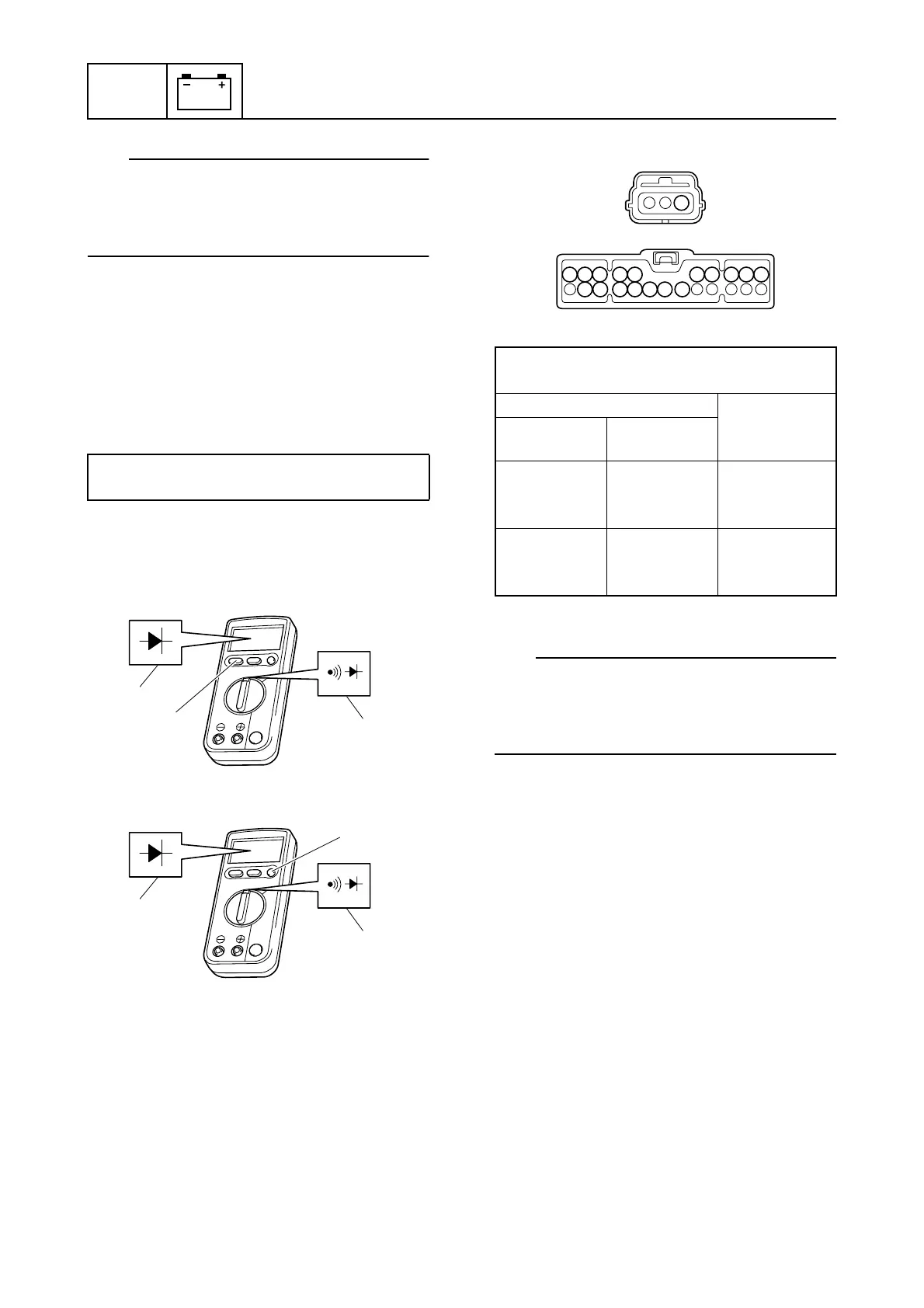
18. Set the digital circuit tester to the mea-
surement range p, and then push the
switch r to display the mark s.
È Tester model CD721
É Tester model CD731a
19. Check the wiring harness for continuity.
OL: Indicates an overload
TIP:
Make sure that there is continuity between
terminal 1 of the cam position sensor coupler
c and one of the terminals of the fuse holder
coupler m.
20. Connect the fuse holder coupler, and
then install fuse holder.
21. Install the intake manifold (STBD). See
“Installing the intake manifold” (6-18).
22. Connect the cam position sensor cou-
plers.
23. Install the engine ECM cover.
Checking the OCV
1. Check the operation of the OCVs using
the YDIS “Stationary test” and check the
operating sound. See “Function” (4-2).
2. Remove the flywheel magnet cover, and
then disconnect the OCV couplers a
and b.
Engine ECM bolt:
7 N·m (0.7 kgf·m, 5.2 ft·lb)
p
s
r
È
p
s
r
É
Wiring harness continuity
(testing diode mode):
Tester probe Display value
(reference
data)
m Terminals
1–10 and
16–22
c Terminal 1 0.514 V
c Terminal 1
m Terminals
1–10 and
16–22
OL
1
9
10
22 21 20 19 18 17 16
8 7 6 5 4 3 2 1
c
m

 Loading...


