5-34
5
7. Install the intake silencer. See “Installing
the intake silencer” (6-19).
8. Remove the intake manifold (STBD).
See “Removing the intake manifold” (6-
17).
9. Remove the fuse holder 1, and then dis-
connect the fuse holder couplers d and
e.
10. Check the wiring harness for continuity.
TIP:
Make sure that there is continuity between
terminal 66 of the engine ECM coupler c
and one of the terminals of the fuse holder
coupler e.
11. Connect the fuse holder couplers, and
then install the fuse holder.
12. Install the intake manifold (STBD). See
“Installing the intake manifold” (6-18).
13. Connect the engine ECM couplers.
NOTICE: Make sure that the rubber
seal is installed properly in each
engine ECM coupler.
14. Install the engine ECM, and then tighten
the engine ECM bolts to the specified
torque.
15. Install the engine ECM cover.
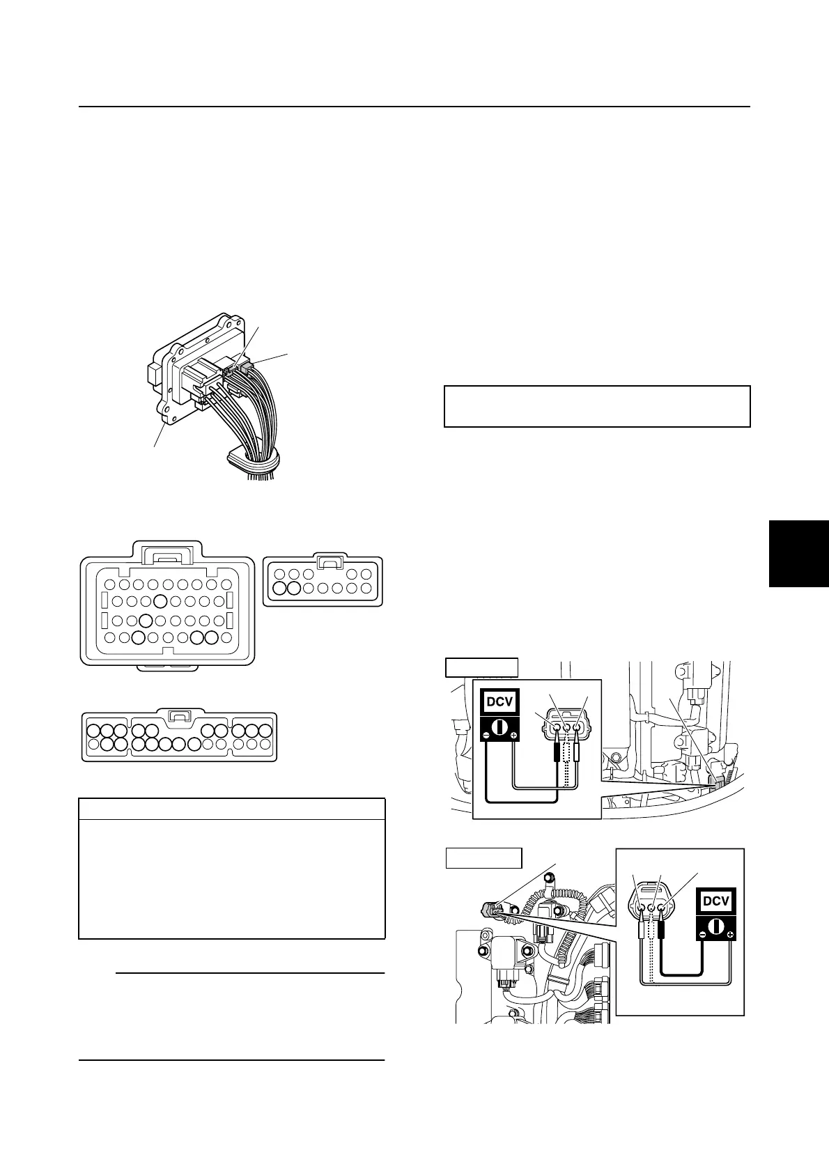
Checking the cam position sensor
1. Remove the engine ECM cover.
2. Disconnect the cam position sensor cou-
plers a, b, and c.
3. Turn the engine start switch to ON, and
then measure the input voltage at the
cam position sensor coupler.
Wiring harness continuity:
c Terminal 66–
e Terminals 1–10 and 16–22
c Terminal 79–d Terminal 11
c Terminal 80–d Terminal 12
c Terminal 75–Ground
c Terminal 84–Ground
1
d
e
dc
e
84
66
75
80
79
1112
9
10
22 21 20 19 18 17 16
8 7 6 5 4 3 2 1
Engine ECM bolt:
7 N·m (0.7 kgf·m, 5.2 ft·lb)
a
R/Y
W/B
B
STBD IN
PORT IN
b
R/Y
W/G
B
Engine control system and component

 Loading...


