5-46
5
15. Install the intake manifold (STBD). See
“Installing the intake manifold” (6-18).
16. Connect the fuel injector couplers, and
then install the fuel rail covers.
Checking the low-pressure fuel
pump and high-pressure fuel pump
1. Check the operation of the low-pressure
fuel pump and high-pressure fuel pump
using the YDIS “Stationary test” and
check the operating sound. See “Func-
tion” (4-2).
2. Remove the intake silencer. See
“Removing the intake silencer” (6-17).
3. Disconnect the low-pressure fuel pump
coupler a.
4. Turn the engine start switch to ON, and
then measure the input voltage at the
low-pressure fuel pump coupler.
5. Turn the engine start switch to OFF.
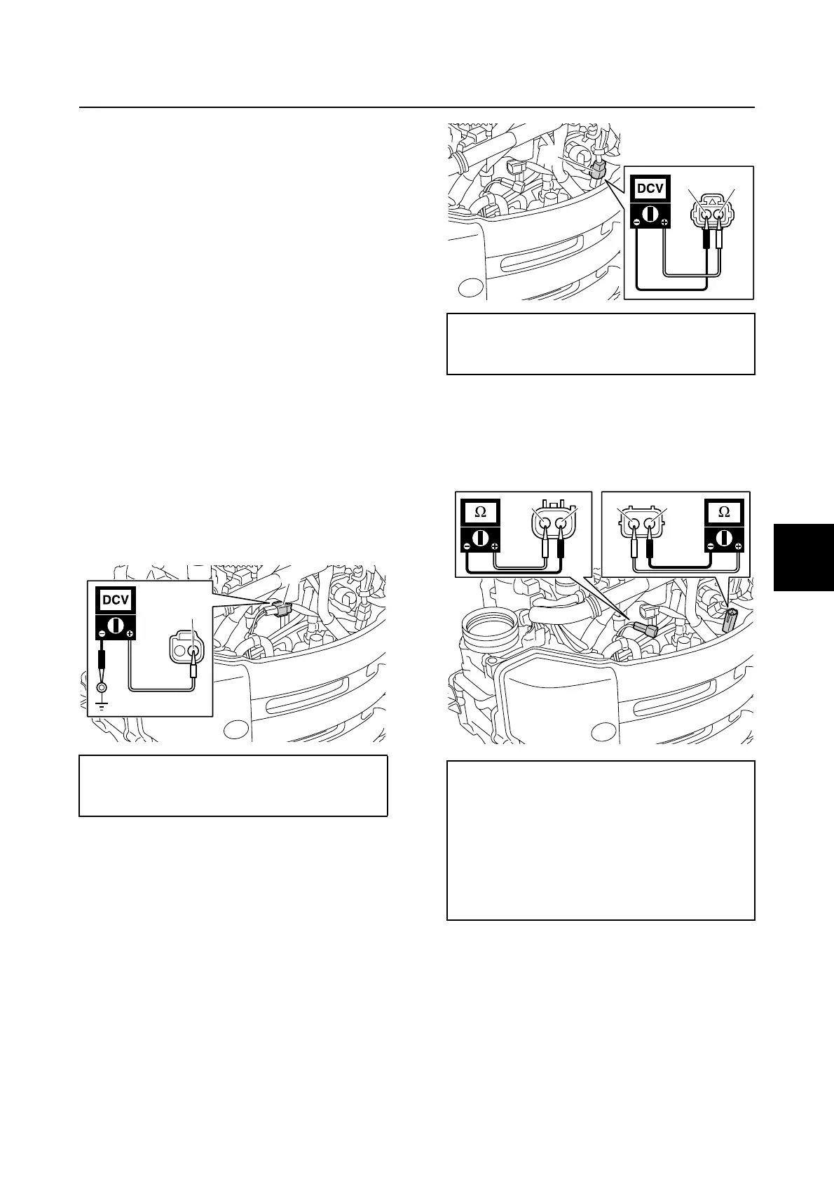
6. Disconnect the vapor separator wiring
harness extension coupler b.
7. Connect the tester probes to the termi-
nals of the vapor separator wiring har-
ness extension coupler b, and then
measure the input voltage within 5 sec-
onds after turning the engine start switch
to ON.
8. Turn the engine start switch to OFF.
9. Measure the resistance of the fuel pump
motors.
10. Remove the intake manifold (STBD).
See “Removing the intake manifold” (6-
17).
11. Remove the fuse holder 1, and then dis-
connect the fuse holder coupler c.
Low-pressure fuel pump input voltage:
Red/Yellow (R/Y)–Ground
12.0 V (battery voltage)
R/Y
a
High-pressure fuel pump input voltage:
Red (R)–Black (B)
12.0 V (battery voltage)
Low-pressure fuel pump resistance
(reference data):
Red (R)–Black (B)
0.5–4.0 Ω at 20 °C (68 °F)
High-pressure fuel pump resistance
(reference data):
Red (R)–Black (B)
0.3–10.0 Ω at 20 °C (68 °F)
RB
b
R B R B
Fuel control unit and component

 Loading...


