7-90
7
TIP:
Do not place the Plastigauge (PG-1) over the
oil hole in the crankpin of the crankshaft.
4. Install the connecting rod a and con-
necting rod cap b onto the crankpin c.
TIP:
• When checking the oil clearance, reuse the
removed connecting rod bolts.
• Make sure that the protrusions d on the
connecting rod a and connecting rod cap
b face toward the flywheel magnet end of
the crankshaft.
• Do not turn the connecting rod until the
crankpin oil clearance measurement has
been completed.
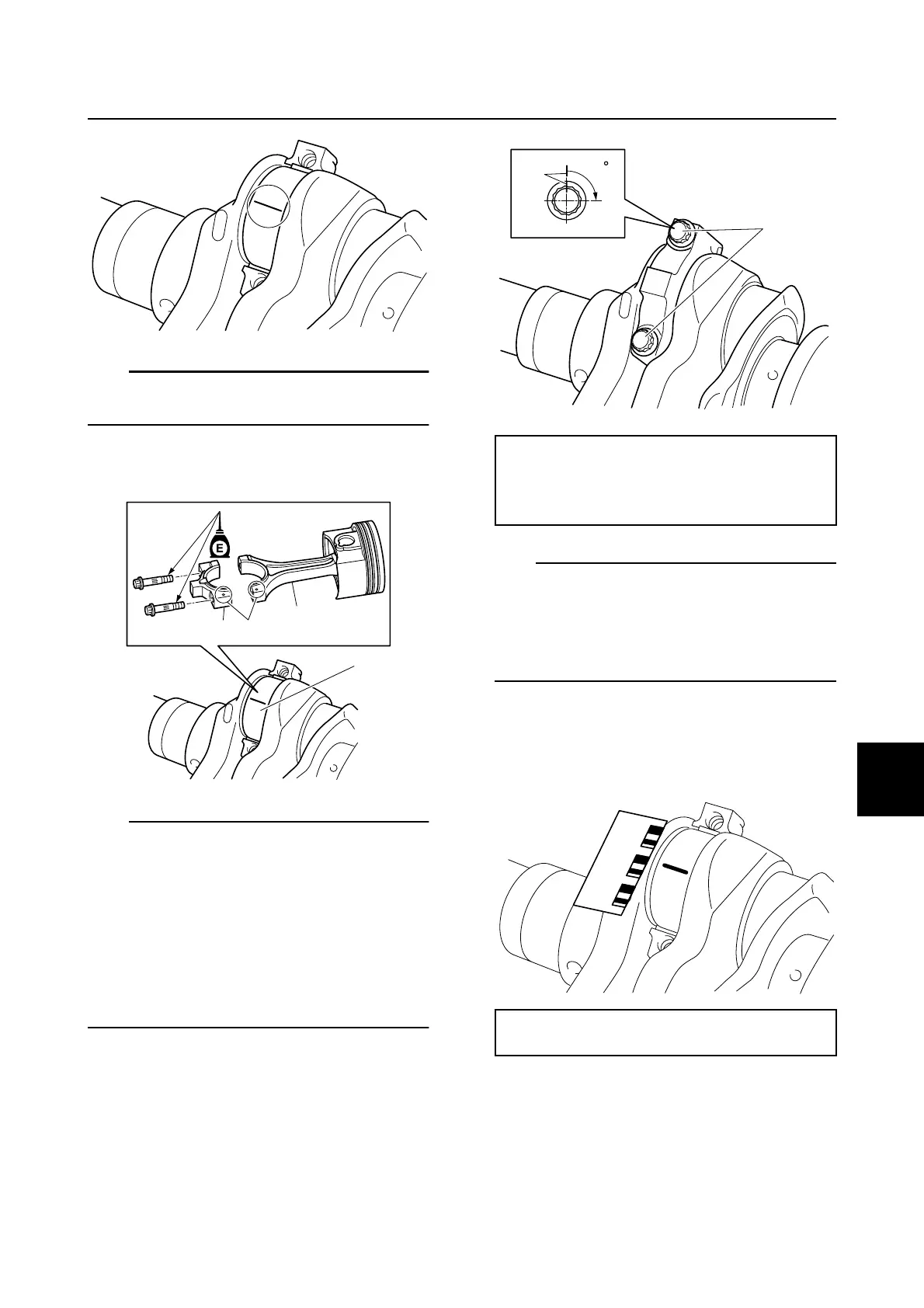
5. Tighten the connecting rod bolts 2 to the
specified torques in 3 stages.
TIP:
In the 3rd tightening stage for the connecting
rod bolts 2, mark the connecting rod bolts
and the connecting rod cap with identification
marks e, and then tighten the bolts 90° from
the marks on the connecting rod cap.
6. Remove the connecting rod cap, and
then measure the width of the com-
pressed Plastigauge (PG-1) on the
crankpin.
Selecting the crankpin bearing
When replacing the crankpin bearing, select
the bearing as follows:
1. Check the crankpin mark a on the
crankshaft.
c
b
a
d
Connecting rod bolt 2:
1st: 13 N·m (1.3 kgf·m, 9.6 ft·lb)
2nd: 23 N·m (2.3 kgf·m, 17.0 ft·lb)
3rd: 90°
Crankpin oil clearance:
0.028–0.066 mm (0.0011–0.0026 in)
90
e
2
Cylinder block

 Loading...


