7-92
7
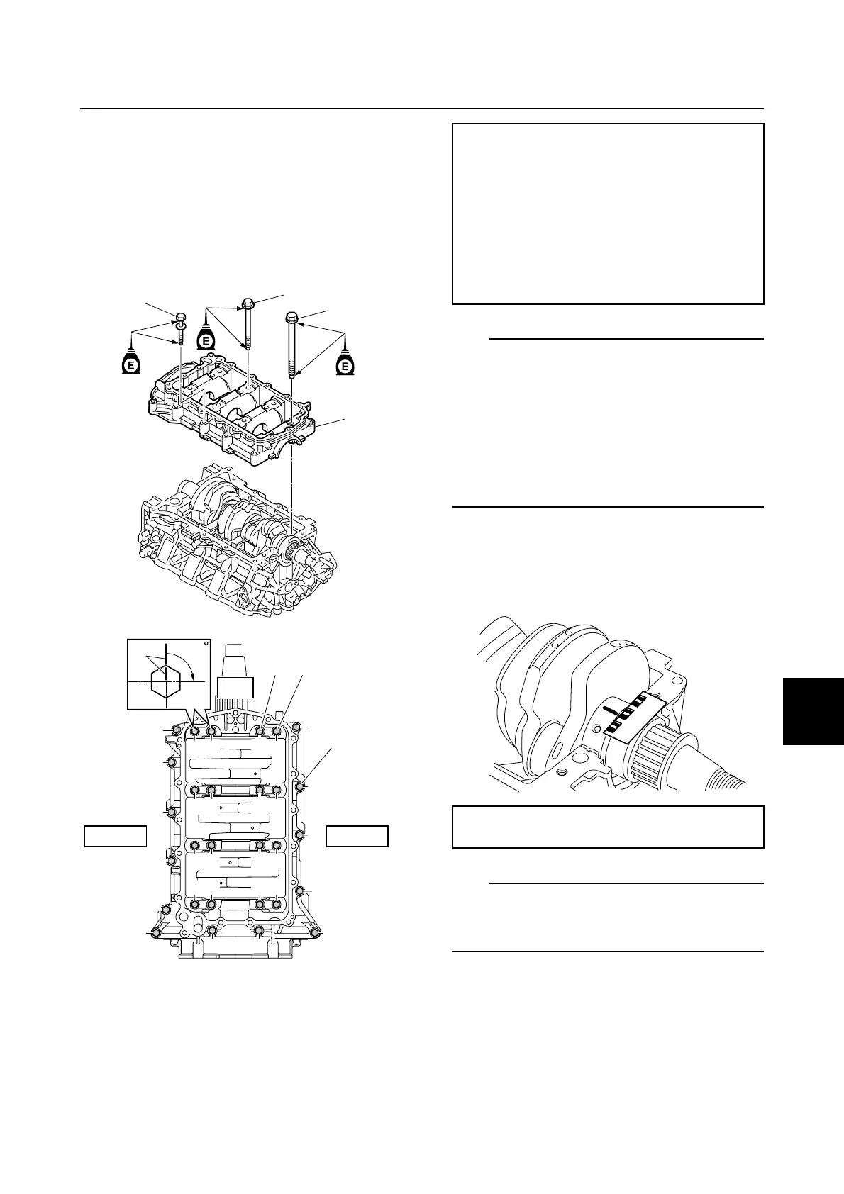
6. Install the crankcase 4, and then tighten
the crankcase bolts 5 and 6 to the
specified torques in 2 stages and in the
order 1, 2, and so on.
7. Tighten the crankcase bolts 7 to the
specified torques in 2 stages and in the
order G, H, and so on.
TIP:
• Do not turn the crankshaft until the crank-
shaft journal oil clearance measurement
has been completed.
• In the 2nd tightening stage for the M8 bolts
5 and M10 bolts 6, mark the bolts and the
crankcase with identification marks c, and
then tighten the bolts 90° from the marks on
the crankcase.
8. Remove the crankcase, and then mea-
sure the width of the compressed Plasti-
gauge (PG-1) on each crankshaft
journal.
TIP:
When loosening the crankcase bolts, loosen
them in the opposite order used for tighten-
ing.
Selecting the crankshaft journal
bearing
When replacing the crankshaft journal bear-
ing, select the bearing as follows:
6
4
5
7
PORT
UP
STBD
90
c
12
34
56
78
90
AB
CD
EF
G
H
I
J
K
L
MN
O
P
Q
R
S
6
7
5
Crankcase bolt 5 1–8 (M8):
1st: 28 N·m (2.8 kgf·m, 20.7 ft·lb)
2nd: 90°
Crankcase bolt 6 9–F (M10):
1st: 33 N·m (3.3 kgf·m, 24.3 ft·lb)
2nd: 90°
Crankcase bolt 7 G–S (M8):
1st: 14 N·m (1.4 kgf·m, 10.3 ft·lb)
2nd: 28 N·m (2.8 kgf·m, 20.7 ft·lb)
Crankshaft journal oil clearance:
0.035–0.050 mm (0.0014–0.0020 in)
Cylinder block
 Loading...