5-61
ELEC
Electrical system
11. Check the wiring harness for continuity.
12. Connect the engine ECM couplers.
NOTICE: Make sure that the rubber
seal is installed properly in each
engine ECM coupler.
13. Install the engine ECM, and then tighten
the engine ECM bolts to the specified
torque.
14. Install the engine ECM cover.
15. Connect the thermoswitch connectors.
16. Install the flywheel magnet cover.
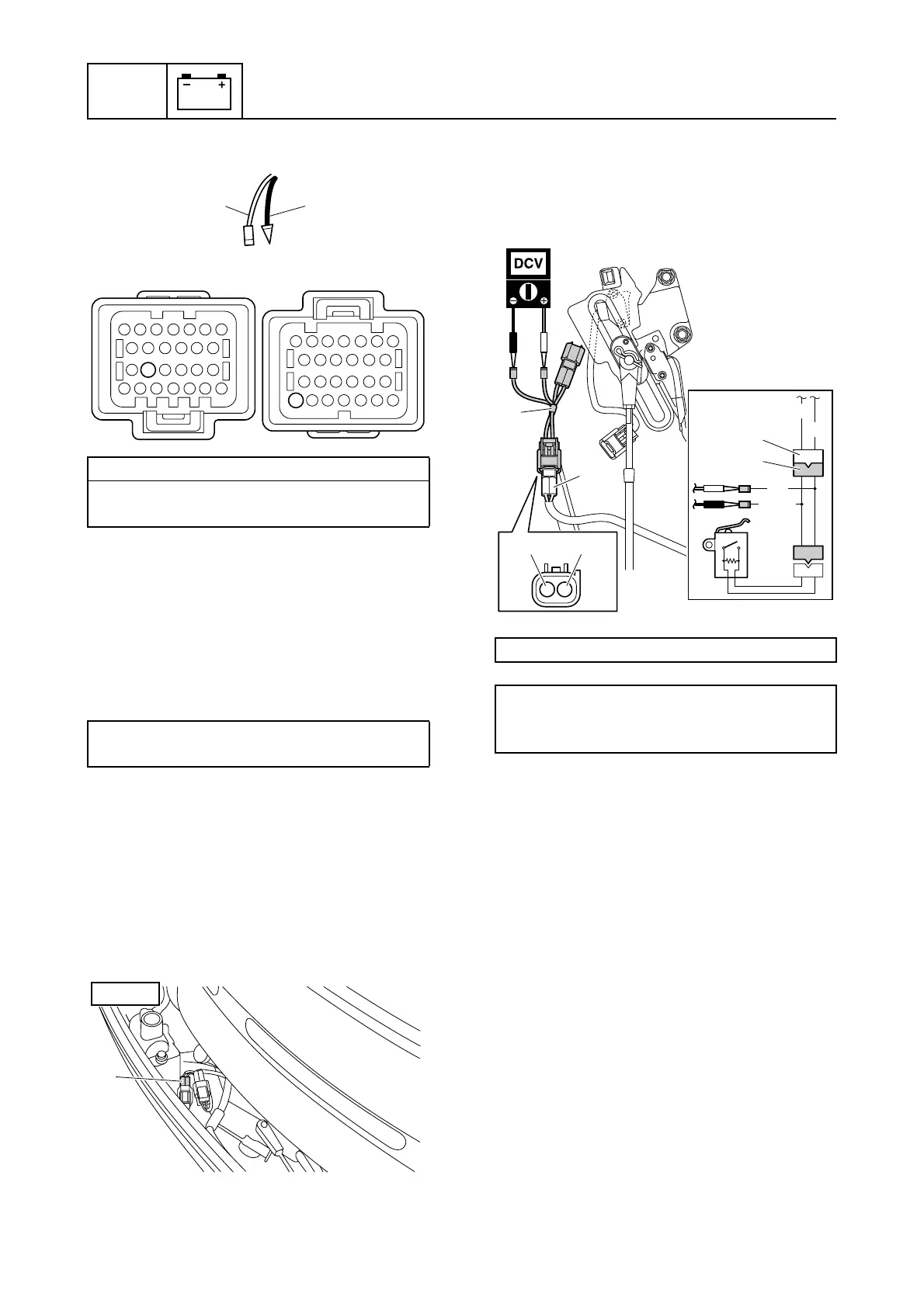
Checking the shift cut switch
1. Disconnect the shift cut switch coupler
a.
2. Connect the special service tool 1 to the
shift cut switch coupler a.
3. Turn the engine start switch to ON, and
then measure the input voltage.
4. Turn the engine start switch to OFF.
5. Disconnect the special service tool 1,
and then connect it to the shift cut switch
coupler b.
6. Measure the shift cut switch resistance
when the gear shift is in the N position.
Wiring harness continuity:
Pink (P)–m Terminal 52
Black (B)–k Terminal 18
Engine ECM bolt:
7 N·m (0.7 kgf·m, 5.2 ft·lb)
km
18
52
P
B
a
STBD
Test harness (2 pins) 1: 90890-06867
Shift cut switch input voltage:
Blue/Yellow (L/Y)–Black (B)
4.75–5.25 V
1
a
G/W
G
1
a
B
L/Y
B L/Y

 Loading...


