7-4
7
21. Install the spark plugs, and then tighten
them to the specified torque.
22. Install the ignition coils, and then tighten
the ignition coil bolts to the specified
torque.
23. Install the wiring harness to the engine
ECM bracket. See steps 26–36 in
“Installing the wiring harness” (7-23).
24. Install the speed sensor to the bracket.
See step 17 in “Installing the power unit”
(7-11).
25. Install the blowby hose. See “Installing
the intake silencer” (6-19).
26. Install the engine ECM cover and fly-
wheel magnet cover.
Adjusting the valve clearance
Adjust the valve clearances when the engine
is cold.
When the timing belt is not installed, do
not turn the flywheel magnet or driven
sprockets. Otherwise, the pistons and
valves or intake and exhaust valves could
collide with each other and be damaged.
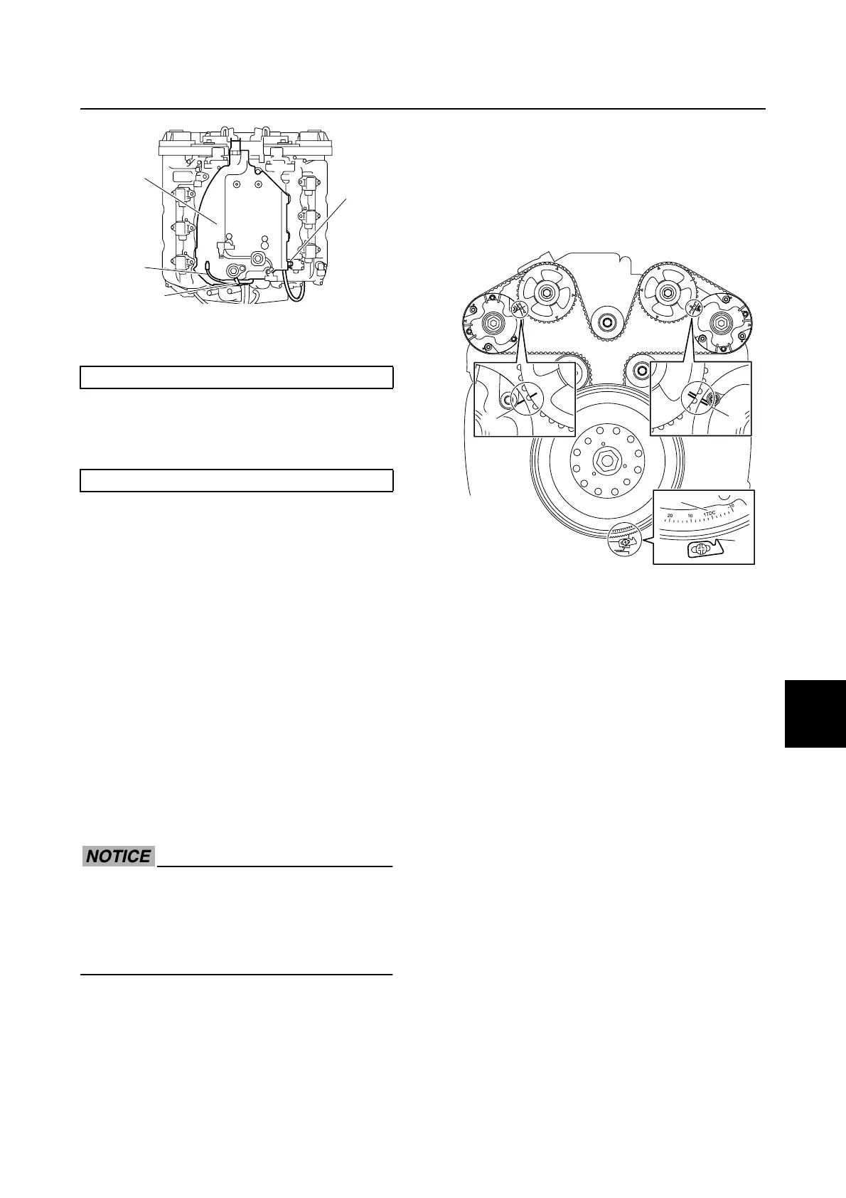
1. Check that the “1TDC” mark a on the
flywheel magnet and the pointer b are
aligned.
2. Check that the “II” marks c on the VCT
assembly (PORT) and driven sprocket
(PORT) are aligned, and check that the
“I” marks d on the VCT assembly
(STBD) and driven sprocket (STBD) are
aligned.
3. Remove the intake manifolds. See
“Removing the intake manifold” (6-17).
4. Disconnect the quick connectors. See
steps 3–5 in “Disconnecting the quick
connector” (6-7).
5. Remove the fuel hoses and fuel rail cov-
ers.
6. Remove the flywheel magnet and stator
assembly. See “Removing the flywheel
magnet” (7-16).
7. Remove the wiring harness and wiring
harness guide. See steps 17–29 in
“Removing the wiring harness” (7-20).
8. Remove the timing belt. See steps 9–11
in “Removing the timing belt” (7-38).
9. Remove the VCT assemblies, driven
sprockets, and camshafts. See “Remov-
ing the driven sprocket and camshaft” (7-
48).
Spark plug: 25 N·m (2.5 kgf·m, 18.4 ft·lb)
Ignition coil bolt: 7 N·m (0.7 kgf·m, 5.2 ft·lb)
2
3
a
1
a
b
c
d
Power unit (check and adjustment)

 Loading...


