5-51
ELEC
Electrical system
8. Install the intake manifold (STBD). See
“Installing the intake manifold” (6-18).
Checking the Rectifier Regulator
Do not connect the battery cables in
reverse. Otherwise, the Rectifier Regula-
tor could be damaged.
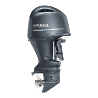
1. Remove the fuse cover 1.
2. Measure the Rectifier Regulator output
peak voltage.
TIP:
Do not use peak voltage adapter B when
measuring the Rectifier Regulator output
peak voltage.
3. Install the fuse cover.
4. Remove the intake manifold (STBD).
See “Removing the intake manifold” (6-
17).
5. Remove the fuse holder, and then dis-
connect the Rectifier Regulator couplers
and ground lead.
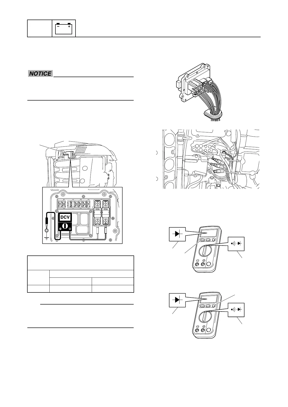
6. Set the digital circuit tester to the mea-
surement range a, and then push the
switch b to display the mark c.
È Tester model CD721
É Tester model CD731a
Rectifier Regulator output peak voltage:
Fuse (60 A)–Ground
r/min
Loaded
1500 3500
DC V 13.0 13.0
1
a
b
È
c
É
a
c
b
 Loading...