5-47
ELEC
Electrical system
12. Remove the engine ECM cover.
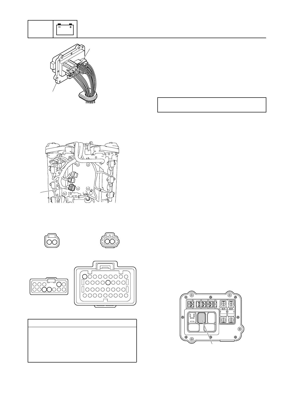
13. Remove the engine ECM, and then dis-
connect the engine ECM coupler d.
14. Check the wiring harness for continuity.
15. Connect the engine ECM coupler.
NOTICE: Make sure that the rubber
seal is installed properly in the engine
ECM coupler.
16. Install the engine ECM, and then tighten
the engine ECM bolts to the specified
torque.
17. Install the engine ECM cover.
18. Connect the fuse holder coupler, and
then install the fuse holder.
19. Install the intake manifold (STBD). See
“Installing the intake manifold” (6-18).
20. Connect the low-pressure fuel pump cou-
pler and vapor separator wiring harness
extension coupler.
21. Install the intake silencer. See “Installing
the intake silencer” (6-19).
Checking the high-pressure fuel
pump relay
1. Remove the intake manifold (STBD).
See “Removing the intake manifold” (6-
17).
2. Remove the fuse cover and relay cover,
and then remove the high-pressure fuel
pump relay 1. NOTICE: Be careful not
to damage the relay.
3. Check the high-pressure fuel pump relay.
See step 3 in “Checking the main relay”
(5-27).
Wiring harness continuity:
a Terminal 1–c Terminal 2
a Terminal 2–d Terminal 61
b Terminal 1–c Terminal 10
b Terminal 2–Ground
c Terminal 9–d Terminal 65
1
c
d
d
a
b
c
61
65
2
9
10
2 1
1
2
Engine ECM bolt:
7 N·m (0.7 kgf·m, 5.2 ft·lb)
1

 Loading...


