2-10
2
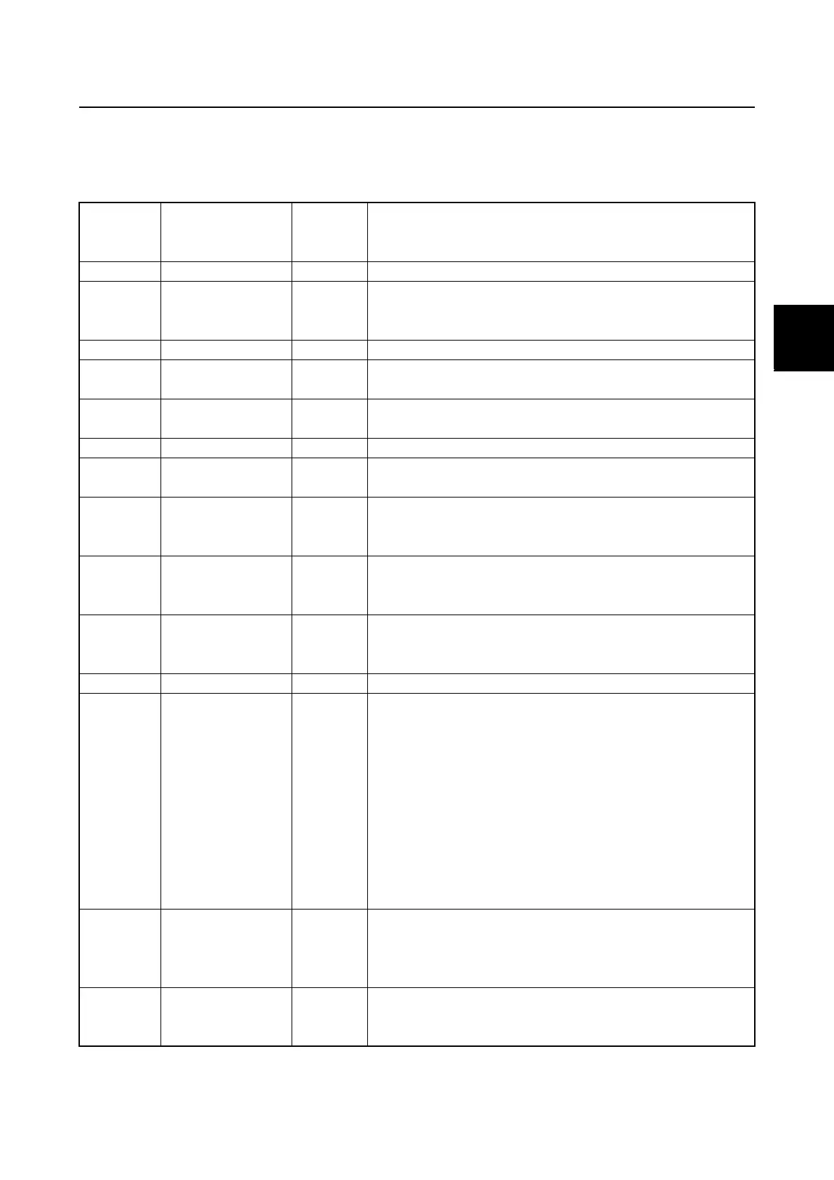
Fail-safe control
In fail-safe control, the engine ECM enters the fail-safe mode when an electrical component mal-
functions. The fail-safe control system records the trouble codes according to the engine trouble
conditions.
Trouble
code
Item
LAN
gauge
display
Trouble conditions to be detected
13 Pulser coil C/E No signal
15
Engine
temperature
sensor
C/E
Open or short circuit in the engine temperature sensor
circuit. Output voltage is less than 0.18 V or more than
4.90 V.
17 Knock sensor C/E Output voltage is less than 0.90 V or more than 4.00 V.
23
Air temperature
sensor
C/E
Output voltage is less than 0.10 V or more than 4.60 V.
24, 71,
72
Cam position
sensor
C/E
Signal error (irregular)
28 Neutral switch C/E Neutral switch is off during the start-up mode.
29
Air pressure
sensor
C/E
Output voltage is less than 0.20 V or more than 4.50 V.
39
Oil pressure
sensor C/E
Output voltage is less than 0.30 V, more than 4.80 V
for 260 seconds, or more than 4.80 V when the engine
is stopped.
45
Shift cut switch
C/E
Output voltage is more than 4.50 V, the shift cut switch
is on during the start-up mode, or both the neutral
switch and shift cut switch are on for 5 seconds.
46
Thermoswitch
C/E
Switch is on when the engine temperature is 40 °C
(104 °F) or less, or off when the engine temperature is
more than 120 °C (248 °F).
73, 74 OCV C/E Open or short circuit in the OCV circuit.
112, 113,
114, 115,
116, 117,
118, 119,
121, 122,
123, 129,
136, 137,
138, 139,
141, 142,
143, 144,
145
ETV
C/E
Open or short circuit in the ETV relay and ETV motor
circuit.
124, 125,
126, 127,
128
TPS
C/E
TPS 1 output voltage is less than 0.35 V or more than
4.80 V, TPS 2 output voltage is less than 2.25 V or
more than 4.80 V, or the output voltage difference
between TPS 1 and TPS 2 is 2.30 V or more.
131, 132,
133, 134,
135
APS
C/E
Open or short circuit in the APS circuit, or the output
voltage difference between APS 1 and APS 2 is 0.996
V or more.
Electronic control system

 Loading...


